


by 


Welcome to this definitive technical analysis of the FAW J6P Valve Train, the complete “engine breathing” and “engine braking” system for the FAW Jiefang CA3250P66K2L1T1E 6×4 diesel dump truck.
This is not just a collection of parts; it is a complex “Logic Assembly” engineered for two primary purposes: precision airflow control and powerful, integrated vehicle retardation.
The “logic” of this FAW J6P Valve Train is to perfectly choreograph the flow of air into and out of the engine’s cylinders, a task that dictates 100% of the engine’s power, efficiency, and emissions.
The most critical “Design Logic” of this specific FAW J6P Valve Train is its integration of a powerful “engine brake” (Jake Brake). This is not an “exhaust brake,” but a true “compression-release” brake. This system, which includes components like the ‘Pressure valve-rocker arm’ (Comp 17), uses high-pressure engine oil to force the exhaust valves open during the compression stroke, turning the engine into a massive air compressor. This “Braking Logic” is essential for a heavy-duty dump truck, as it provides huge amounts of braking force without using the service (wheel) brakes, saving them from overheating and fading on long, steep descents.
This expert guide is an essential resource for engine rebuilders, fleet technicians, and parts managers. We will deconstruct the entire 25-component group into its four primary “logic” systems: the “Valve Actuation Logic” (the rocker arms and shafts that move the valves), the critical “Engine Brake Logic” (the high-pressure valves and pins), the “Valve Sealing & Guide Logic” (the components inside the head), and the “Spring & Retention Logic” (the parts that close the valves). This is the complete guide to the FAW J6P Valve Train.
This group forms the “bridge” of the FAW J6P Valve Train. In an OHV (cam-in-block) engine, these components transfer the “lift” from the camshaft (via pushrods, not shown) to the tops of the valves.
1. Components: ‘Rocker shaft assy’ (1007130-29D) & ‘Rocker shaft support’ (1007102-29D, 1007101-29D)
This is the “structural foundation” of the valvetrain. The ‘Rocker shaft assy’ (Comp 12) is a hardened, hollow steel shaft. Its “logic” is twofold: 1) It provides the rigid, precision-ground axle that the rocker arms pivot on. 2) Its “hollow logic” is that it acts as the primary “oil galley,” delivering high-pressure oil from the head to lubricate the rocker arms and to *power* the engine brake system. This shaft is held in place by 5 ‘Rocker shaft supports’ (Comp 11) and 1 ‘Rear support’ (Comp 15), which are bolted to the cylinder head.
2. Components: ‘Rocker arm-intake’ (1007121-29D) & ‘Rocker arm-exhaust’ (1007111-48D)
These (Comp 4 & 8) are the “levers” of the FAW J6P Valve Train. Their “Multiplier Logic” is to act as a lever to multiply the cam’s lift. A 1.5:1 ratio, for example, means that for every 10mm the pushrod moves, the valve opens 15mm. This allows for aggressive valve lift with a smoother cam profile. The ‘Intake’ and ‘Exhaust’ rockers are different; the exhaust rocker (Comp 8) is a more complex component, as it must house the “Engine Brake Logic” (see Core 2).
3. Components: ‘Locking nut-valve adj. screw’ (1007113-29D) & ‘Adjusting screw-rocker arm’ (1007112-29D)
This (Comp 3 & 5) is the “Serviceability Logic” of the FAW J6P Valve Train. The ‘Adjusting screw’ (Comp 5) sits at the end of the rocker arm (pushrod side). Its “logic” is to allow a technician to precisely set the “valve lash”—the tiny, critical gap (e.g., 0.015 inches) in the system. This gap is necessary to compensate for thermal expansion. The ‘Locking nut’ (Comp 3) locks the screw in place. Incorrect lash is a primary cause of noise, power loss, and FAW J6P Valve Train failure.
This is the most advanced “logic” in this FAW J6P Valve Train, a feature essential for a heavy-duty dump truck. This is *not* an exhaust brake.
1. The “Compression-Release” Logic:
The “logic” of a “Jake Brake” is to turn the engine into an air compressor. When the brake is activated, a solenoid (not listed) sends high-pressure engine oil into the ‘Rocker shaft’ (Comp 12). This oil flows into the ‘Rocker arm-exhaust’ (Comp 8) and acts on the ‘Pressure valve-rocker arm’ (Comp 17). This “Hydraulic Logic” opens the valve, which pushes on a “slave piston” inside the rocker arm. This slave piston then *opens the exhaust valve* near the top of the compression stroke. This instantly releases all the compressed air, forcing the engine to “waste” its power. This creates a powerful, 200+ hp braking effect, saving the wheel brakes.
2. Components: ‘Pressure valve’ (1007117-29D), ‘Ball seat’ (1007118-29D), & ‘Limit pin’ (1007103-29D)
This is the “high-pressure” sub-assembly. The ‘Pressure valve’ (Comp 17) is the hydraulic “trigger.” The ‘Ball seat’ (Comp 18) is the pivot for the valve-actuating part of the rocker. The ‘Limit pin’ (Comp 7) is a “stop” that controls the travel of the engine brake mechanism. This entire system is what separates a standard FAW J6P Valve Train from a “heavy-duty” FAW J6P Valve Train.
This group of components is located *inside* the cylinder head, but they are all critical, serviceable parts of the FAW J6P Valve Train.
1. Components: ‘Intake valve seat’ (1007016-36D) & ‘Exhaust valve seat’ (1003013-36D)
This is the “Combustion Sealing Logic.” The valves must seal against a perfectly round, incredibly hard surface. The cylinder head is too soft for this. The “logic” here is to press-fit two different types of ‘Valve seats’ (Comp 24 & 25) into the head. The ‘Exhaust valve seat’ (Comp 25) is made of a very hard, high-temperature steel alloy (like Stellite) to withstand superheated exhaust. The ‘Intake valve seat’ (Comp 24) is a different hardened steel, cooled by the intake air. Their “service logic” is that they are “sacrificial” and can be re-ground or replaced.
2. Component: ‘Valve guide’ (1003014-29D)
This (Comp 23) is the “Precision Guide Logic.” The list calls for 24 guides (12 intake, 12 exhaust). Their “logic” is to be a replaceable, low-friction sleeve (often bronze alloy) that is press-fit into the head. This guide is what holds the valve stem in perfect alignment as it moves up and down 15+ times per second. A worn valve guide will cause high oil consumption and poor valve sealing.
3. Component: ‘Valve guide oil seal assy’ (1007035-29D)
This (Comp 22) is the “Oil Control Logic.” This is a small, spring-loaded rubber seal that snaps onto the top of the valve guide. Its “logic” is to allow a *microscopic* film of oil to travel down the valve stem for lubrication, but to prevent the “bath” of oil splashing around the FAW J6P Valve Train from being *sucked* into the engine on the intake stroke. Failed valve seals are a primary cause of blue smoke and oil consumption.
EXPLAIN:
This final group’s “logic” is to ensure the valves *close* quickly and completely, and to keep the entire assembly locked together at high RPM.
1. Component: ‘Exhaust valve spring’ (1007022-29D)
This (Comp 21) is the “Closing Force Logic.” The list calls for 12, one for each exhaust valve (intake springs are not on this list, but are similar). The “logic” of this heavy-duty spring is to provide enough force to slam the valve shut against the high-pressure exhaust gas, perfectly sealing the cylinder. It must also be “tuned” to the correct frequency to prevent “valve float”—a condition at high RPM where the spring can’t keep up and the valve fails to close, leading to a collision with the piston.
2. Component: ‘Valve spring seat’ (1007024-29D)
This (Comp 20) is the “Protection Logic.” The list calls for 24 (one for each valve). The FAW J6P Cylinder Head is made of a softer metal (cast iron or aluminum). The “logic” of this hardened steel “seat” is to sit *between* the spring and the head, preventing the high-pressure spring from “chewing” or “digging” its way into the head casting over millions of cycles.
3. Component: ‘Valve cotter’ (1007028-29D)
This (Comp 19) is the “Retention Logic.” The list calls for 48 (two for each valve). These are the two tiny, wedge-shaped “keepers” that lock into a groove at the top of the valve stem. The “logic” is that the spring’s force (pushing up on the retainer, not listed) forces these two cotters *together*, creating a “taper-lock” that holds the entire spring assembly onto the valve. These tiny parts are the only thing preventing the valve from dropping into the cylinder, which would destroy the entire FAW J6P Valve Train and engine.
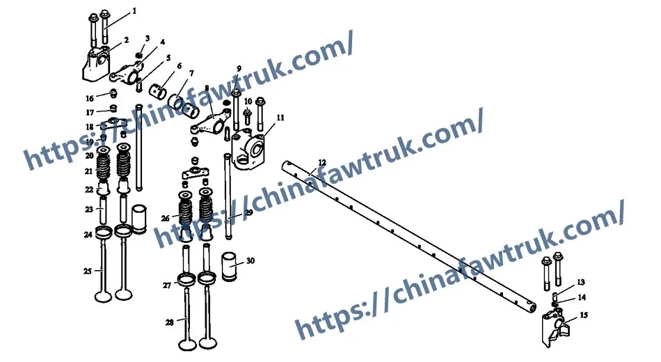
The following table provides the complete, detailed breakdown of all 25 component types in the FAW J6P Valve Train assembly (with Engine Brake) for the FAW Jiefang CA3250P66K2L1T1E 6×4 dump truck.
| Mark | Part No. | Part Name | Quantity |
|---|---|---|---|
| 1 | Q1820880 | Hexagon flange bolt | 10 |
| 2 | 1007104-29D (1007104B29D) | Bolt-rocker shaft support | 1 M8x20 |
| 3 | 1007113-29D | Locking nut-valve adjusting screw | 12 |
| 4 | 1007121-29D | Rocker arm-intake | 6 |
| 5 | 1007112-29D | Adjusting screw-rocker arm | 12 |
| 6 | 1007114-29D (1007114A29D) | Bushing-rocker arm | 12 |
| 7 | 1007103-29D | Limit pin-rocker arm | 12 |
| 8 | 1007111-48D (1007111-621-0000) | Rocker arm-exhaust | 6 |
| 9 | 1007106-48D (1007106A621-0000) | Bolt-rocker shaft support | 4 |
| 10 | Q1840835 | Hexagon flange bolt | 5 |
| 11 | 1007102-29D | Rocker shaft support | 5 |
| 12 | 1007130-29D (1007130A29D) | Rocker shaft assy | 1 |
| 13 | GB/T71-1985 | Slotted countersunk head screw M8x20 | 1 |
| 14 | Q340B08T12 | Type I hexagon nut | 1 |
| 15 | 1007101-29D | Rocker shaft rear support | 1 |
| 16 | 1007117-29D | Pressure valve-rocker arm | 12 |
| 17 | 1007118-29D | Ball seat-rocker arm | 12 |
| 18 | 1007012-29D (1007012-29DA) | Crosshead (Fully interchangeable) | 12 |
| 19 | 1007028-29D | Valve cotter | 48 |
| 20 | 1007024-29D | Valve spring seat | 24 |
| 21 | 1007022-29D | Exhaust valve spring | 12 |
| 22 | 1007035-29D (1007035A29D) | Valve guide oil seal assy | 24 |
| 23 | 1003014-29D (1003014M29D) | Valve guide | 24 |
| 24 | 1003013-36D | Exhaust valve seat | 12 |
| 25 | 1007016-36D | Intake valve seat | 12 |
The specifications for the FAW J6P Valve Train are defined by its dual function as an OHV actuation system and a compression-release engine brake.
| Vehicle Application | FAW Jiefang CA3250P66K2L1T1E 6×4 Dump Truck |
| System Group | FAW J6P Valve Train / Valvetrain Assembly |
| System Type | Overhead Valve (OHV) / Cam-in-Block |
| Key Feature | Integrated Compression-Release Engine Brake |
| Actuation Logic | ‘Rocker shaft assy’ (1007130-29D) with ‘Rocker arms’ |
| Engine Brake Logic | ‘Pressure valve-rocker arm’ (1007117-29D) – Qty 12 |
| Valve Control | ‘Crosshead’ (1007012-29D) – (For 4-valve-per-cylinder design) |
| Wear Component (Guide) | ‘Valve guide’ (1003014-29D) – Qty 24 |
| Wear Component (Sealing) | ‘Intake/Exhaust valve seat’ (1007016-36D / 1003013-36D) – Qty 24 total |
| Oil Control Logic | ‘Valve guide oil seal assy’ (1007035-29D) – Qty 24 |
| Retention Logic | ‘Valve cotter’ (1007028-29D) – Qty 48 |
| Associated System | Full FAW J6P Valve Train and Cylinder Head |
FAW parts, including the Cylinder Block Assembly, are packaged with care to ensure safe delivery. Each component is secured in protective materials to prevent damage during transit. The logistics network guarantees timely shipments worldwide, supporting efficient maintenance operations. Below is an image illustrating the standard packaging for FAW truck parts, showcasing the attention to detail in handling and storage.

This packaging approach minimizes the risk of corrosion or impact damage, ensuring that parts like the FAW Cylinder Block Assembly arrive in perfect condition. Customers can rely on FAW’s logistics for consistent quality and reliability.


