


by 


Welcome to this expert deconstruction of the FAW J6P Crankcase Ventilation system. This is the complete “engine breathing” and “oil separation” assembly for the FAW Jiefang CA3250P66K2L1T1E 6×4 dump truck.
This is not just a simple hose; it is a complex 14-component “Logic Assembly” engineered to handle the engine’s “blow-by.”
The “logic” of this FAW J6P Crankcase Ventilation system is to safely vent crankcase pressure, *separate* the oil mist from that gas, *return* the liquid oil to the pan, and *route* the clean gas back into the intake to be burned.
The “Separation Logic” of this FAW J6P Crankcase Ventilation system is its most critical feature. All piston engines have “blow-by”—hot, high-pressure gas that leaks past the piston rings. This gas is contaminated with a heavy “mist” of hot oil. If this mist is vented into the intake, it will “coke” the turbocharger and foul the intake valves, leading to a massive loss of power. If it is vented to the atmosphere, it is a major environmental pollutant. This system, centered on the ‘Oil-gas separator assy’ (Comp 6), is designed to “scrub” this gas clean.
This technical guide is an essential resource for engine technicians, fleet managers, and parts specialists. We will deconstruct the entire 14-component-type group. We will analyze the “Separation Logic” (the main separator unit), the “Plumbing & Flow Logic” (the various pipes for dirty gas, clean gas, and oil return), the “Sealing Logic” (the gaskets), and the “Structural & Fastener Logic” that holds the entire FAW J6P Crankcase Ventilation system together and isolates it from vibration.
This component is the “brain” of the FAW J6P Crankcase Ventilation system. Its entire purpose is to separate liquid oil from the blow-by gas.
1. Component: ‘Oil-gas separator assy’ (1014010-70AB1)
This (Comp 6) is the core of the assembly. It is not an empty box. Its “Baffle Logic” is an internal “maze” or “cyclonic” path. The “dirty” blow-by gas (mixed with oil mist) enters the separator at high speed.
The “Impact & Coalescence Logic” is how it works. The heavy liquid oil droplets have too much inertia to make the sharp turns of the maze. They “impact” the baffle walls. As they do, they “coalesce” (merge into heavier drops) and drip to the bottom of the separator. The “clean” gas (which is now just vapor) is light enough to make the turns and exits from a separate “clean” port. This is the primary function of the FAW J6P Crankcase Ventilation unit.
A failure or clog in this separator is a major problem. If it clogs, the crankcase will pressurize, blowing out the main oil seals. If its internal baffles fail, it will allow liquid oil to be “sucked” into the engine’s intake, leading to blue smoke, high oil consumption, and the rapid “coking” (carbon buildup) of the turbocharger and intake valves.
This group forms the “pathway” of the FAW J6P Crankcase Ventilation system, moving the gas and oil to their correct locations.
1. Component: ‘Connecting pipe assy – ventilation’ (1014029-48D)
This (Comp 11) is the “Dirty Side Logic.” This pipe’s function is to collect the “dirty,” oil-mist-laden blow-by gas (usually from the cylinder head cover) and transport it *to* the ‘Oil-gas separator’ (Comp 6). It must be a large-diameter, free-flowing pipe.
2. Component: ‘Ventilation pipe assy’ (1014025-59D)
This (Comp 12) is the “Clean Side Logic.” After the separator (Comp 6) has “scrubbed” the gas, this pipe’s “logic” is to transport the *clean* gas (now just vapor) *from* the separator and route it *back* into the engine’s air intake (usually just before the turbocharger). This “Closed-Loop Logic” is what makes it an emissions-control device, as it allows these unburnt hydrocarbons to be re-burned by the engine.
3. Component: ‘Oil return pipe – Oil-gas separator’ (1014022-B29D)
This (Comp 8) is the “Drain Logic.” This is a critical, but often overlooked, part of the FAW J6P Crankcase Ventilation system. Its “logic” is to be the one-way “drain” for all the liquid oil that “coalesces” at the bottom of the separator (Comp 6). This pipe routes that captured oil *back* to the engine’s oil pan, returning it to the lubrication system. A clog in this small pipe is a common failure point that will cause the entire separator to fill with oil, which is then sucked into the “clean side” (Comp 12), causing massive oil consumption and blue smoke.
This group’s “logic” is to ensure the FAW J6P Crankcase Ventilation system is both structurally sound and perfectly airtight.
1. Component: ‘Support – Oil-gas separator’ (1014021-48D)
This (Comp 2) is the “Anti-Vibration Logic.” The ‘Oil-gas separator’ (Comp 6) is a relatively heavy component, and it cannot just “hang” off its pipes. This “support” is a heavy-duty steel bracket. Its “logic” is to securely bolt the separator assembly to the engine block, isolating it from the engine’s vibrations and preventing the plastic housing or pipe connections from cracking.
2. Components: ‘Gasket – Oil-gas separator’ (1014014-70A) & ‘Gasket – …support’ (1014017-70A)
These (Comp 1 & 5) are the “Sealing Logic.” This is an “airtight” system. Any leak *after* the air filter is a major problem, as it will suck in dirty, unfiltered air *into* the engine. These gaskets “logic” is to provide a perfect, flexible, oil-resistant seal at the main connection points (e.g., where the separator bolts to the cylinder head cover or block). A leak here will cause a “vacuum leak” code and feed abrasive dust directly into the engine, destroying the FAW J6P Crankcase Ventilation system’s function.
This final group’s “logic” is to provide a secure, vibration-proof connection for all components of the FAW J6P Crankcase Ventilation system.
1. The “Hose Clamp” Logic (Components 7, 9, 10)
The system uses four (4) ‘Worm-drive soft pipe clamps’ (Comp 7 & 10) and two (2) ‘Pipe clamps’ (Comp 9). The “logic” of these clamps is to provide a 360-degree, “Airtight Clamp” on the flexible hose sections (like the ‘Oil return pipe’, Comp 8). This ensures a positive seal that will not leak oil (on the drain side) or suck air (on the ventilation side), even as the rubber hoses heat-cycle and harden over time.
2. The “Bolt” Logic (Components 3, 4, 13, 14)
This is the “Structural Fastener Logic.” The system uses five (5) ‘Combination bolts’ (Comp 3 & 4) and two (2) ‘Hex flange bolts’ (Comp 13 & 14) with their associated washers. The “Combination” and “Flange” bolt “logic” is that the built-in washer distributes the clamping load and resists vibration. This is what keeps the ‘Support’ (Comp 2) for the FAW J6P Crankcase Ventilation separator from shaking loose, ensuring the assembly’s long-term reliability.
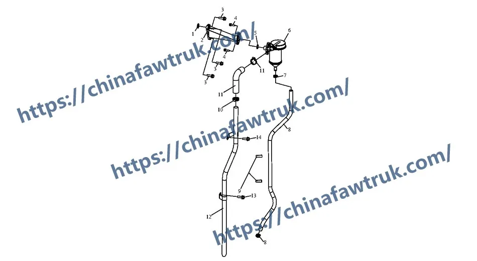
The following table provides the complete, detailed breakdown of all 14 component types in the FAW J6P Crankcase Ventilation assembly for the FAW Jiefang CA3250P66K2L1T1E 6×4 dump truck.
| Mark | Part No. | Part Name | Quantity |
|---|---|---|---|
| 1 | 1014014-70A (1014014A600-0367) | Gasket – Oil-gas separator | 1 |
| 2 | 1014021-48D (1014021B621-0000) | Support – Oil-gas separator | 1 |
| 3 | CQ1460830 | Combination bolt | 3 |
| 4 | CQ1460625 | Combination bolt | 2 |
| 5 | 1014017-70A (1014036-29D) | Gasket – Oil-gas separator support | 1 |
| 6 | 1014010-70AB1 (1014010A600-0367) | Oil-gas separator assy | 1 |
| 7 | Q676B16 | Worm-drive soft pipe clamp B-type | 2 |
| 8 | 1014022-B29D (1014022-630-0000) | Oil return pipe – Oil-gas separator | 1 |
| 9 | 1014031-48D (1014031-621-0000) | Pipe clamp | 2 |
| 10 | Q676B29 | Worm-drive soft pipe clamp B-type | 2 |
| 11 | 1014029-48D | Connecting pipe assy – ventilation | 1 |
| 12 | 1014025-59D (1014025B630-0000) | Ventilation pipe assy | 1 |
| 13 | Q1841020 Q40110 | Hexagon flange bolt Washer | 1 1 |
| 14 | Q1840816 Q40108 | Hexagon flange bolt Washer | 1 1 |
The specifications for the FAW J6P Crankcase Ventilation system are defined by its function as a closed-loop, oil-separating emissions device.
| Vehicle Application | FAW Jiefang CA3250P66K2L1T1E 6×4 Dump Truck |
| System Group | FAW J6P Crankcase Ventilation (PCV) System |
| Primary Logic | Oil/Gas Separation (Blow-by Treatment) |
| Secondary Logic | Crankcase De-pressurization, Emissions Control, Oil Recovery |
| Core Component | ‘Oil-gas separator assy’ (1014010-70AB1) |
| Inlet Pipe (Dirty Gas) | ‘Connecting pipe assy – ventilation’ (1014029-48D) |
| Outlet Pipe (Clean Gas) | ‘Ventilation pipe assy’ (1014025-59D) |
| Drain Pipe (Recovered Oil) | ‘Oil return pipe’ (1014022-B29D) |
| Mounting System | ‘Support’ (1014021-48D) & ‘Gaskets’ (1014014-70A, 1014017-70A) |
| Securing System | ‘Worm-drive soft pipe clamp’ (Q676B16, Q676B29) |
| Failure Mode | Clogged drain/separator leads to high oil consumption and seal failure. |
FAW parts, including the Cylinder Block Assembly, are packaged with care to ensure safe delivery. Each component is secured in protective materials to prevent damage during transit. The logistics network guarantees timely shipments worldwide, supporting efficient maintenance operations. Below is an image illustrating the standard packaging for FAW truck parts, showcasing the attention to detail in handling and storage.

This packaging approach minimizes the risk of corrosion or impact damage, ensuring that parts like the FAW Cylinder Block Assembly arrive in perfect condition. Customers can rely on FAW’s logistics for consistent quality and reliability.


