


by 


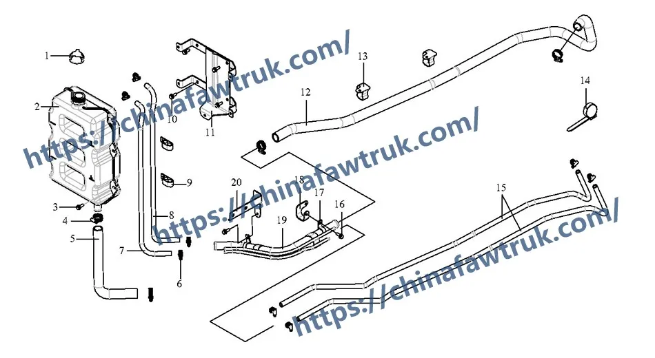
This is a complete technical deconstruction of the FAW J6P Water Filler Cap assembly (Chapter 38). This component, also known as the ‘Pressure cap assy’ (Comp 1), is the most critical “Smallest Serviceable Unit” for the entire cooling system on the FAW Jiefang CA3250P66K2L1T1E 6×4 dump truck. It is not a simple “cap”; it is an active “safety valve” and the “brain” of the system’s physics.
The FAW J6P Water Filler Cap has a “Dual-Valve Logic” that is essential for preventing engine damage. Its first “logic” is “Pressurization.” By sealing the system and holding pressure (e.g., 15 PSI), it “raises the boiling point” of the coolant from 100°C to ~120°C, preventing “flash boiling” in the hot cylinder heads.
Its second “logic” is “Vacuum Relief.” When the engine cools, the coolant contracts, creating a powerful vacuum. The FAW J6P Water Filler Cap has a secondary valve that “opens” to allow coolant/air *in* from the ‘Expansion tank’ (Comp 2), preventing this vacuum from “collapsing” and destroying the radiator hoses.
This guide is a vital resource for all technicians, as a failed FAW J6P Water Filler Cap is often misdiagnosed as a “major” overheating problem. We will deconstruct all 20 parts in this assembly, analyzing the “Pressure Logic” (the cap itself), the “Reservoir Logic” (the tank it sits on), the “Plumbing Logic” (the hoses it controls), and the “Mounting Logic” (the brackets that secure it).
This component *is* the FAW J6P Water Filler Cap. It is the single most important component in this entire assembly for regulating the physics of the cooling system.
1. Component: ‘Pressure cap assy’ (1304010-50A)
This (Comp 1) is the “Boiling Point Logic.” A heavy-duty diesel engine (like the one in the FAW J6P) operates under such high load that its coolant temperature often exceeds the 100°C (212°F) boiling point of water (at sea level).
The FAW J6P Water Filler Cap is a “spring-loaded” valve. It “seals” the ‘Expansion tank assy’ (Comp 2) and the entire cooling system, allowing pressure to build up. This “Pressurization Logic” (e.g., to 1.0 bar / 15 PSI) “tricks” the coolant, raising its boiling point to ~120°C (~250°F).
This “Anti-Boil Logic” is what prevents “flash boiling” or “steam pockets” from forming in the cylinder head, which would immediately stop heat transfer and cause the aluminum head to warp or crack.
The “Dual-Valve Logic” of the FAW J6P Water Filler Cap:
1. Main Pressure Valve (Outward): This is the “Safety Logic.” A large spring holds this valve shut (e.g., at 15 PSI). If the pressure gets *too high* (e.g., from a failing head gasket), this valve “vents” the excess pressure *out*, preventing the “FAW J6P Radiator” (Chapter 37) or hoses from exploding.
2. Vacuum Relief Valve (Inward): This is the “Implosion-Proof Logic.” When the engine is shut off, the 90°C coolant cools and “contracts,” creating a powerful “vacuum.” This “vacuum” would “suck” the ‘Radiator outlet hose’ (Chapter 37) completely flat, “imploding” it. The FAW J6P Water Filler Cap has a second, smaller, “inward” valve that “opens” under this vacuum, drawing coolant *back in* from the ‘Expansion tank’ (Comp 2) to keep the system full and at neutral pressure.
The FAW J6P Water Filler Cap (Comp 1) does not mount to the radiator. It mounts to this component, the ‘Expansion tank assy’.
1. Component: ‘Expansion tank assy’ (1311020-76A)
This (Comp 2) is the “Reservoir Logic” and the “Air-Trap Logic.” It is the “lung” of the cooling system. Its “logic” is to provide the “empty space” (from the “MIN” to “MAX” line) that the expanding, hot coolant needs to “flow into.”
This is also the “Degassing Logic” center. All the small “degas” hoses (Comp 7, 8, 15) from the engine and radiator “terminate” here. They “dump” air bubbles into this tank, where internal baffles “separate” the air from the coolant.
The “Symbiotic Logic” is that the FAW J6P Water Filler Cap (Comp 1) *must* be at the “highest point” of the system, which is this tank. This allows the “scavenged” air to be vented *out* of the system by the ‘Pressure cap’ when needed. This “cap-on-tank” design is the “Active Thermal Management” logic of the entire FAW J6P cooling system.
This group represents all the “Smallest Serviceable Units” (SSU) that “feed” the expansion tank that the FAW J6P Water Filler Cap controls.
1. The “Degas & Return” Logic (Hoses & Pipes)
This network of “plumbing” is the “arterial system” for the tank. It includes the ‘Degas hose’ (Comp 7, 8, 15) and the ‘Return water hose’ (Comp 5, 12). This “logic” is to “transport” the air and coolant to/from the ‘Expansion tank’ (Comp 2).
2. The “Sealing” Logic (Clamps)
This is the “Leak-Proof Logic.” It includes ‘Banjo-type hose clamp B model’ (Comp 4, 6), ‘Hose clamp’ (Comp 13), and ‘Single pipe clamp’ (Comp 17). The “Banjo-type” (T-Bolt) clamps are the “high-torque” clamps. A single failed clamp (e.g., Comp 6) means a “catastrophic coolant loss.”
3. The “Anti-Chafe” Logic (Clamps & Ties)
This is the “Vibration-Proofing Logic.” It includes the ‘Dual pipe clamp assy’ (Comp 9) and the ‘Plastic zip tie’ (T67420376) (Comp 14).
The six (6) ‘Plastic zip ties’ (Comp 14) are “Deliberate Engineering Logic.” Their “logic” is to “anchor” the small, flexible ‘Degas hoses’ (Comp 7, 8, 15) to the chassis, preventing them from “chafing” (rubbing) against the vibrating engine. A “chafed” hose will leak, drain the system, and render the FAW J6P Water Filler Cap‘s function useless, leading to overheating.
This final group provides the “context” for the FAW J6P Water Filler Cap. The cap must be accessible to the driver and “isolated” from vibration.
1. The “Support” Logic (Components 11, 18, 20)
The ‘Expansion tank bracket assy’ (1311040-61C) (Comp 11), ‘Bracket assy’ (1311070-14B) (Comp 18), and ‘Bracket assy’ (1311075-14B) (Comp 20) form the “structural cage” for the ‘Expansion tank’ (Comp 2).
This “Mounting Logic” is what “locks” the polymer tank (and the FAW J6P Water Filler Cap on top of it) to the rigid steel chassis of the dump truck, preventing “fatigue cracks” from vibration.
2. The “Fastener” Logic (Components 3, 10, 16)
The ‘Combination bolt’ (CQ1460825) is the “Hardware Logic.” A total of eleven (11) of these bolts (5 + 4 + 2) are used to “secure” these brackets to the frame. These “flanged” (self-locking) bolts are “Vibration-Proof Logic,” ensuring the entire assembly (tank, cap, and all) never rattles loose.
The following table provides the complete, detailed breakdown of all 20 component types in the FAW J6P Water Filler Cap and expansion tank assembly (Chapter 38) for the FAW Jiefang CA3250P66K2L1T1E 6×4 dump truck.
| Mark | Part No. | Part Name | Quantity |
|---|---|---|---|
| 1 | 1304010-50A | Pressure cap assy | 1 |
| 2 | 1311020-76A | Expansion tank assy | 1 |
| 3 | CQ1460825 | Combination bolt | 5 |
| 4 | CQ67640B | Banjo-type hose clamp B model | 4 |
| 5 | 1311033-61B | Rear return water hose | 1 |
| 6 | CQ67622B | Banjo-type hose clamp B model | 8 |
| 7 | 1311068-61B | Degas hose | 1 |
| 8 | 1311069-61B | Rear degas hose | 1 |
| 9 | 1311060-61B | Dual pipe clamp assy | 2 |
| 10 | CQ1460825 | Combination bolt | 4 |
| 11 | 1311040-61C | Expansion tank bracket assy | 1 |
| 12 | 1311033-14B | Return water hose | 1 |
| 13 | 1311077-61B | Hose clamp | 2 |
| 14 | T67420376 | Plastic zip tie | 6 |
| 15 | 1311036-14B | Degas hose | 2 |
| 16 | CQ1460825 | Combination bolt | 2 |
| 17 | 1311071A377 | Single pipe clamp | 2 |
| 18 | 1311070-14B | Bracket assy | 1 |
| 19 | 1311065-14B | Rear return water steel pipe assy | 1 |
| 20 | 1311075-14B | Bracket assy | 1 |
The specifications for the FAW J6P Water Filler Cap system are defined by its function as the active pressure and vacuum regulator for the entire cooling circuit.
| Vehicle Application | FAW Jiefang CA3250P66K2L1T1E 6×4 Dump Truck |
| System Group | FAW J6P Water Filler Cap & Expansion Tank Assembly |
| Primary Logic | System Pressurization (Boiling Point Elevation) |
| Secondary Logic | Vacuum Relief (Anti-Collapse) & Pressure Venting (Safety) |
| Core Component | ‘Pressure cap assy’ (1304010-50A) |
| Associated Reservoir | ‘Expansion tank assy’ (1311020-76A) |
| Degas Plumbing | 1311068-61B, 1311069-61B, 1311036-14B |
| Sealing Hardware | Banjo-type Clamps (CQ67640B, CQ67622B) |
| Anti-Chafe Hardware | ‘Plastic zip tie’ (T67420376) – Qty 6 |
| Mounting Hardware | ‘Expansion tank bracket assy’ (1311040-61C) |
FAW parts, including the Cylinder Block Assembly, are packaged with care to ensure safe delivery. Each component is secured in protective materials to prevent damage during transit. The logistics network guarantees timely shipments worldwide, supporting efficient maintenance operations. Below is an image illustrating the standard packaging for FAW truck parts, showcasing the attention to detail in handling and storage.

This packaging approach minimizes the risk of corrosion or impact damage, ensuring that parts like the FAW Cylinder Block Assembly arrive in perfect condition. Customers can rely on FAW’s logistics for consistent quality and reliability.


