


by 


Welcome to this complete technical analysis of the FAW J6P Upper Cover assembly, the “command and control” center for the CA10TA160M manual transmission. This guide is for the FAW Jiefang CA3250P66K2L1T1E 6×4 dump truck, deconstructing all 31 components, from the main FAW J6P Upper Cover casting to every interlock pin and shift fork.
The FAW J6P Upper Cover is the “brain” of the manual gearbox. Its logic is to house the entire shift rail mechanism, translating the driver’s hand movements into the precise mechanical action of the shift forks. It also contains the critical interlock system that prevents mis-shifts and protects the gearbox from damage.
This group represents the foundational “chassis” of the entire shift mechanism. All 30 other components in this list are mounted *inside* or *onto* this single part, the FAW J6P Upper Cover.
1. Component: ‘Upper cover’ (1702026-A7G)
This (Comp 1) is the FAW J6P Upper Cover itself. This is a heavy-duty, complex component, precision-cast from iron or aluminum. Its logic is threefold:
The Alignment Logic is its most critical function. The FAW J6P Upper Cover is machined with multiple, perfectly parallel bores. These bores are the “tunnels” that support the three main “Shift fork shafts” (Comp 17, 24, 29). Any warping or damage to this cover will cause the shafts to bind, making shifting difficult or impossible.
The Sealing Logic is its second function. This component acts as the “lid” for the entire gearbox, sealing the top opening of the main case and keeping the high-temperature gear oil contained. This seal is created by a gasket and the numerous bolts (Comp 5, 12, 15) that provide clamping force.
The Mounting Logic is its third function. The FAW J6P Upper Cover provides the threaded holes and mounting bosses for all the system’s sensors, like the ‘Neutral indicator switch’ (Comp 7) and ‘Reverse light switch’ (Comp 11).
2. Component: ‘Lifting lug’ (1702096-A7G)
This (Comp 14) is a heavy-duty steel bracket bolted to the FAW J6P Upper Cover. Its Service Logic is to provide a strong, balanced attachment point for an engine hoist, allowing a technician to safely lift the entire, heavy transmission assembly out of the truck chassis.
3. Component: ‘Oil guide groove’ (1702083-A7G) & ‘Plugs’ (Comp 2, 6)
The ‘Oil guide groove’ (Comp 4) is a small but clever component inside the FAW J6P Upper Cover, designed to channel “splashed” oil directly onto the shift rails to keep them lubricated. The ‘Hex socket tapered plugs’ (Comp 2, 6) are used to seal any machining or service ports in the casting.
This group represents the complete mechanical assembly, housed within the FAW J6P Upper Cover, that is responsible for engaging First and Reverse gears.
1. Components: ‘Shift fork shaft – 1st/Rev’ (1702041-A7G) & ‘Shift fork – 1st/Rev’ (1702046-A7G)
This (Comp 17 & 16) is the core 1st/Reverse linkage. The ‘Shift fork shaft’ (Comp 17) is the hardened steel rod that slides fore-and-aft inside the FAW J6P Upper Cover. The ‘Shift fork’ (Comp 16) is the rigid lever that is locked onto this shaft.
The Actuation Logic is simple: the driver’s gear lever moves this shaft (Comp 17) forward or backward. The fork (Comp 16) moves with it, and its “tines” engage the ‘Sliding gear sleeve’ (on the Second Axis) to lock either the 1st gear or the Reverse gear.
2. The “Detent” Group (Comp 18, 19, 20, 21)
This group includes: ‘Plug – 1st/Rev shift fork’ (Comp 18), ‘Spring – plunger’ (Comp 19), ‘Plunger – 1st/Rev’ (Comp 20), and ‘Locking screw’ (Comp 21).
The Positioning Logic is the function of this sub-assembly. The ‘Shift fork shaft’ (Comp 17) has three small “V” grooves machined into it (one for 1st, one for Neutral, one for Reverse).
The ‘Spring’ (Comp 19) pushes the ‘Plunger’ (Comp 20) with high force into these grooves. This is the “detent” that gives the shift lever its “snap” and “click.” It holds the gear in place and prevents it from popping out under load. This entire assembly is threaded into the FAW J6P Upper Cover.
This group contains the two remaining shift rails and forks, which are also precisely aligned by the FAW J6P Upper Cover.
1. The “2nd/3rd” Group (Comp 23, 24, 25)
This includes: ‘Shift fork – 2nd/3rd’ (Comp 23), ‘Shift fork shaft – 2nd/3rd’ (Comp 24), and ‘Guide block – 2nd/3rd’ (Comp 25).
The Actuation Logic is identical to the 1st/Rev rail. The ‘Shaft’ (Comp 24) slides within the FAW J6P Upper Cover, moving the ‘Fork’ (Comp 23) to engage the 2nd/3rd synchronizer sleeve. The ‘Guide block’ (Comp 25) is a small key that locks the fork to the shaft, forcing them to move as one unit.
2. The “4th/5th” Group (Comp 28, 29, 30)
This includes: ‘Shift fork – 4th/5th’ (Comp 28), ‘Shift fork shaft – 4th/5th’ (Comp 29), and ‘Shift block – 4th/5th’ (Comp 30).
This is the final shift rail assembly. The ‘Shaft’ (Comp 29) slides in the FAW J6P Upper Cover, moving the ‘Fork’ (Comp 28) and its ‘Shift block’ (Comp 30) to engage the 4th/5th synchronizer sleeve. The ‘Shift block’ is the “wear pad” that actually touches the ‘Sliding gear sleeve’.
This group contains the “safety” features of the FAW J6P Upper Cover. Its logic is to A) provide feedback to the driver/ECU, and B) physically prevent a dangerous mis-shift.
1. The “Interlock” Group (Comp 26, 27)
This group includes: ‘Interlock steel ball’ (Comp 26, Qty 2) and ‘Interlock pin’ (Comp 27). These components are *not* detents; they are the “interlock” system.
The Safety Logic is their function. These small pins and balls sit in special cross-drillings *between* the three shift rails (Comp 17, 24, 29) inside the FAW J6P Upper Cover. When one rail moves (e.g., to engage 3rd gear), it pushes these pins and balls sideways. This, in turn, *physically blocks* the other two rails, making it *impossible* for them to move from their neutral position. This FAW J6P Upper Cover interlock system is what prevents a driver from ever engaging two gears at once.
2. The “Detent” Group (Comp 8, 9)
This includes: ‘Self-lock steel ball’ (Comp 8, Qty 3) and ‘Self-lock spring’ (Comp 9, Qty 3). This is the *main* detent system (separate from the plunger in Core 2). One set is used for each of the three shift rails. The springs (Comp 9) push the balls (Comp 8) into the V-grooves on the shafts, providing the “snap” and “click” feel for all gears.
3. The “Sensor” Group (Comp 7, 11)
This group includes: ‘Neutral indicator switch’ (Comp 7) and ‘Reverse light switch assy’ (Comp 11).
The Feedback Logic is their function. These two sensors are threaded into the FAW J6P Upper Cover. Their plungers rest against the shift rails. When the 1st/Rev rail moves to “Reverse,” it depresses the ‘Reverse light switch’ (Comp 11), turning on the truck’s reverse lights. When all rails are in their center position, the ‘Neutral indicator switch’ (Comp 7) is depressed, telling the truck’s ECU (and the driver) that it is safe to start the engine.
This final group contains all the remaining hardware that holds the FAW J6P Upper Cover together and secures the internal components.
1. The “Main Bolts” (Comp 5, 12, 15)
This includes: ‘Hex flange bolt’ (Comp 5, Qty 2), ‘Hexagon bolt’ (Comp 12, Qty 2), and ‘Hexagon bolt’ (Comp 15, Qty 15).
The Clamping Logic is their function. These are the main bolts that fasten the FAW J6P Upper Cover (Comp 1) to the main gearbox housing, compressing the gasket (not listed) to create the vital oil seal. The ‘Spring washer’ (Comp 13) works with these bolts to prevent them from vibrating loose.
2. The “Internal Fasteners” (Comp 22, 31)
This includes: ‘Fastening screw’ (Comp 22, Qty 5) and ‘Steel wire lock line’ (Comp 31, Qty 5).
The Critical Safety Logic is the function of this pair. The five ‘Fastening screws’ (Comp 22) are what lock the shift forks (Comp 16, 23, 28) to their respective shafts (Comp 17, 24, 29).
Because these screws are *inside* the FAW J6P Upper Cover, if one backed out, it would cause a total shift failure. To prevent this, they are “safety-wired.” The ‘Steel wire lock line’ (Comp 31) is threaded through holes in the heads of the screws (Comp 22) and twisted tight, making it physically *impossible* for the screws to ever vibrate loose.
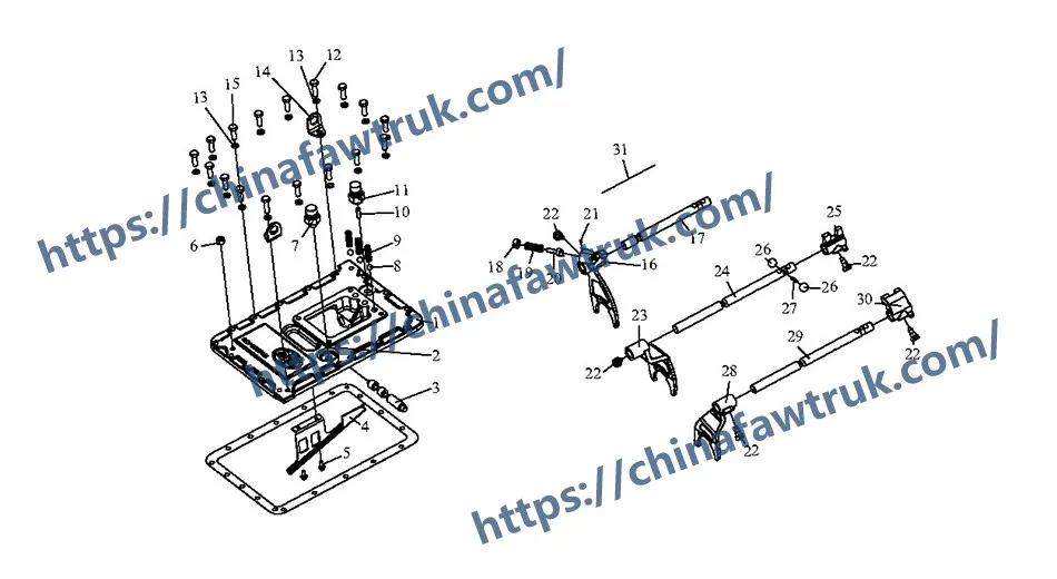
The following table provides the complete, detailed breakdown of all 31 component types in the FAW J6P Upper Cover and shift rail assembly for the FAW Jiefang CA3250P66K2L1T1E 6×4 dump truck.
| Mark | Part No. | Part Name | Quantity |
|---|---|---|---|
| 1 | 1702026-A7G | Upper cover | 1 |
| 2 | Q61901 | Hex socket tapered plug | 1 |
| 3 | 1702076-A7G | Air valve shaft | 1 |
| 4 | 1702083-A7G | Oil guide groove | 1 |
| 5 | Q1840616S | Hexagon flange bolt | 2 |
| 6 | Q61903 | Hex socket tapered plug | 1 |
| 7 | 3774010-367 | Neutral indicator switch | 1 |
| 8 | Q967165 | Self-lock steel ball | 3 |
| 9 | 1702061-A7G | Self-lock spring | 3 |
| 10 | 1702086-A7G | Reverse indicator light switch | 1 |
| 11 | 3729100-71A | Reverse light switch assy | 1 |
| 12 | CQ1501035S | Hexagon bolt | 2 |
| 13 | Q40310 | Spring washer | 17 |
| 14 | 1702096-A7G | Lifting lug | 2 |
| 15 | CQ1501030S | Hexagon bolt | 15 |
| 16 | 1702046-A7G | Shift fork – 1st/Rev | 1 |
| 17 | 1702041-A7G | Shift fork shaft – 1st/Rev | 1 |
| 18 | 1702049-A7G | Plug – 1st/Rev shift fork | 1 |
| 19 | 1702048-A7G | Spring – plunger | 1 |
| 20 | 1702047-A7G | Plunger – 1st/Rev | 1 |
| 21 | 1702051-A7G | Locking screw | 1 |
| 22 | 1702056-A7G | Fastening screw | 5 |
| 23 | 1702037-A7G | Shift fork – 2nd/3rd | 1 |
| 24 | 1702036-A7G | Shift fork shaft – 2nd/3rd | 1 |
| 25 | 1702038-A7G | Guide block – 2nd/3rd | 1 |
| 26 | 1702063-A7G | Interlock steel ball | 2 |
| 27 | 1702064-A7G | Interlock pin | 1 |
| 28 | 1702032-A7G | Shift fork – 4th/5th | 1 |
| 29 | 1702031-A7G | Shift fork shaft – 4th/5th | 1 |
| 30 | 1702033-A7G | Shift block – 4th/5th | 1 |
| 31 | Q50512250 | Steel wire lock line | 5 |
The specifications for the FAW J6P Upper Cover are defined by its function as the complete “command center” for the manual, 5-speed main gearbox, housing all shift rails and interlock systems.
| Vehicle Application | FAW Jiefang CA3250P66K2L1T1E 6×4 Dump Truck |
| System Group | FAW J6P Upper Cover & Shift Rail Assembly |
| Associated Gearbox | CA10TA160M (10-Speed) |
| Primary Logic | Manual Shift Actuation, Sealing, and Rail Alignment |
| Core Component | ‘Upper cover’ (1702026-A7G) |
| Shift Rail Systems | 1st/Reverse, 2nd/3rd, 4th/5th |
| Safety System 1 (Detent) | ‘Self-lock steel ball’ (Q967165) & ‘Spring’ (1702061-A7G) |
| Safety System 2 (Interlock) | ‘Interlock steel ball’ (1702063-A7G) & ‘Pin’ (1702064-A7G) |
| Safety System 3 (Fastener) | ‘Steel wire lock line’ (Q50512250) for ‘Fastening screw’ (1702056-A7G) |
| Sensors (Mounted to Cover) | ‘Neutral indicator switch’ & ‘Reverse light switch assy’ |
| Total Component Types | 31 |
| Associated System | Main Gearbox Internals (Synchronizers, Sleeves) |
FAW parts, including the Cylinder Block Assembly, are packaged with care to ensure safe delivery. Each component is secured in protective materials to prevent damage during transit. The logistics network guarantees timely shipments worldwide, supporting efficient maintenance operations. Below is an image illustrating the standard packaging for FAW truck parts, showcasing the attention to detail in handling and storage.

This packaging approach minimizes the risk of corrosion or impact damage, ensuring that parts like the FAW Cylinder Block Assembly arrive in perfect condition. Customers can rely on FAW’s logistics for consistent quality and reliability.


