


by 


Welcome to this specialized technical analysis of the Sub-Box Left Upper Centre Shaft, a critical component within the CA10TA160M 10-speed transmission. This component is essential for the FAW Jiefang CA3250P66K2L1T1E 6×4 dump truck. This guide deconstructs the 4 components that form the complete Sub-Box Left Upper Centre Shaft assembly for professional service.
The Sub-Box Left Upper Centre Shaft is a high-torque countershaft, or “layshaft,” for the auxiliary (Hi/Lo range) section of the gearbox. Its logic is to receive power from the main box and transmit it to the final output gears, enabling the 10-speed “range split” function that is critical for a heavy-duty dump truck.
This component is the literal foundation of the Sub-Box Left Upper Centre Shaft assembly. It is a single, integrated part that provides the “drive” for the auxiliary gearbox.
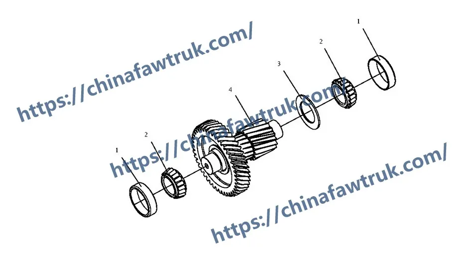
1. Component: ‘Welded intermediate shaft assy – auxiliary box’ (1701515-A7G)
This (Comp 4) is the core component. The name ‘Welded intermediate shaft assy’ (焊接中间轴总成) tells us exactly what it is. This is the Sub-Box Left Upper Centre Shaft itself, and it is a non-serviceable assembly, meaning the gear(s) are permanently welded to the shaft.
The Welded Logic is a design choice for extreme strength. Instead of using splines or keys that can shear under high torque, the manufacturer has welded the gear(s) directly to the shaft. This creates a single, solid piece of steel that can withstand the immense, low-speed torque multiplication of the dump truck’s range box.
The Countershaft Logic is its function. This Sub-Box Left Upper Centre Shaft acts as the “countershaft” or “layshaft” for the auxiliary gearbox. It receives power from the ‘Sub-Box Drive Gear’ (which is connected to the mainshaft) and, in turn, its gear(s) are in constant mesh with the Hi/Lo range gears on the final output shaft.
This Sub-Box Left Upper Centre Shaft is one of several (e.g., Left Upper, Right Upper) that form a robust, power-splitting design. This “multi-countershaft” layout is the key to the CA10TA160M’s high torque capacity, as it distributes the load across multiple gear contact points instead of just one.
This group represents the complete bearing assembly that supports the Sub-Box Left Upper Centre Shaft. A “welded” shaft like this requires a bearing system that can handle immense, multi-directional forces.
1. Component: ‘Tapered roller bearing outer ring’ (306/42-1-1) – Qty 2
This (Comp 1) is the “cup” or “outer race” of the bearing. Two of these are used, one for the front bearing and one for the rear. This cup is precision-machined and is pressed *into the bore* of the auxiliary gearbox housing, where it remains stationary.
2. Component: ‘Tapered roller bearing inner ring’ (306/42-1-2) – Qty 2
This (Comp 2) is the “cone” or “inner ring” of the bearing, which includes the tapered rollers in their cage. This cone is pressed *onto the journals* (ends) of the Sub-Box Left Upper Centre Shaft (Comp 4) and spins with it.
The Tapered Roller Logic is the most important concept for this Sub-Box Left Upper Centre Shaft. Unlike a simple ball bearing (which handles radial loads well) or a thrust washer (which handles axial loads well), a tapered roller bearing is specifically designed to handle *both* massive radial loads (the “pushing” force from the gear mesh) and massive *axial* loads (the “thrust” force generated by helical-cut gears) *at the same time*.
The Opposed Mounting Logic is how they work. The two tapered bearings (Comp 1 + Comp 2) are mounted in “opposition” at the front and rear of the Sub-Box Left Upper Centre Shaft. This creates an extremely rigid assembly that can support the shaft against thrust forces in *both* directions (fore and aft), ensuring perfect gear mesh alignment under all load conditions.
The Service Logic is why they are listed as separate inner and outer rings. They are a “matched set” and must be replaced as one. A technician presses the outer rings into the housing and the inner rings onto the Sub-Box Left Upper Centre Shaft before final assembly.
This final component is one of the most critical parts of the entire Sub-Box Left Upper Centre Shaft assembly. It is a single washer that ensures the longevity of the expensive bearings and shaft.
1. Component: ‘Positioning washer’ (1701518-A7G)
This (Comp 3) is the ‘Positioning washer’. In a tapered roller bearing application, this is not a simple washer; it is a “shim” or “gasket-shim.” Its thickness is precisely controlled, and its function is to set the “bearing pre-load.”
The Pre-load Logic is a high-precision assembly task. Tapered roller bearings cannot be “loose” (with end play), nor can they be “too tight.” They require a specific, slight amount of “squeeze” or “pre-load” to function correctly.
During assembly of the Sub-Box Left Upper Centre Shaft, a technician installs the components and measures the “end play” (the in-and-out movement) with a dial indicator. They then select a ‘Positioning washer’ (Comp 3) of the *exact* thickness required to eliminate that end play and add the correct, specified pre-load (e.g., 0.05mm).
This washer is often placed between a bearing’s outer ring (Comp 1) and the housing or bearing cover. Its thickness is the only thing that guarantees the correct pre-load.
A Sub-Box Left Upper Centre Shaft with incorrect pre-load (e.g., a shim that is too thick or too thin) will suffer catastrophic bearing failure in a very short time. Too tight, and the bearings will overheat and seize. Too loose, and the shaft will “walk” axially, causing the gear teeth to misalign and destroying both the shaft (Comp 4) and the gears it meshes with. Therefore, this ‘Positioning washer’ (Comp 3) is a critical component.
The following table provides the complete, detailed breakdown of all 4 component types in the Sub-Box Left Upper Centre Shaft assembly for the FAW Jiefang CA3250P66K2L1T1E 6×4 dump truck.
| Mark | Part No. | Part Name | Quantity |
|---|---|---|---|
| 1 | 306/42-1-1 | Tapered roller bearing outer ring | 2 |
| 2 | 306/42-1-2 | Tapered roller bearing inner ring | 2 |
| 3 | 1701518-A7G | Positioning washer | 1 |
| 4 | 1701515-A7G | Welded intermediate shaft assy – auxiliary box | 1 |
The specifications for the Sub-Box Left Upper Centre Shaft are defined by its role as a high-load, high-precision countershaft for the auxiliary gearbox.
| Vehicle Application | FAW Jiefang CA3250P66K2L1T1E 6×4 Dump Truck |
| System Group | Sub-Box Left Upper Centre Shaft |
| Associated Gearbox | CA10TA160M (Auxiliary Box Section) |
| Primary Logic | Auxiliary Countershaft / Layshaft |
| Core Component | ‘Welded intermediate shaft assy – auxiliary box’ (1701515-A7G) |
| Shaft Construction | Welded (Gear(s) permanently attached to shaft) |
| Bearing Type | Tapered Roller Bearing (Set of 2) |
| Bearing Components | ‘Outer ring’ (306/42-1-1) & ‘Inner ring’ (306/42-1-2) |
| Pre-load/Positioning | ‘Positioning washer’ (1701518-A7G) |
| Total Component Types | 4 |
| Associated System | Auxiliary Box (Hi/Lo Range) Gear Set |
FAW parts, including the Cylinder Block Assembly, are packaged with care to ensure safe delivery. Each component is secured in protective materials to prevent damage during transit. The logistics network guarantees timely shipments worldwide, supporting efficient maintenance operations. Below is an image illustrating the standard packaging for FAW truck parts, showcasing the attention to detail in handling and storage.

This packaging approach minimizes the risk of corrosion or impact damage, ensuring that parts like the FAW Cylinder Block Assembly arrive in perfect condition. Customers can rely on FAW’s logistics for consistent quality and reliability.


