


par 


Bienvenue dans ce guide technique critique sur le Turbocompresseur FAW (Partie no. 1118010-91W-C00), le composant d'addition de puissance le plus important pour le FAW Jiefang CA4251P66K24T1A3E5 6×4 tracteur semi-remorque diesel. C’est le cœur du système d’admission forcée du moteur.
Le Turbocompresseur FAW est responsable de forcer un volume élevé d’air comprimé dans les cylindres du moteur, permettant une consommation de carburant beaucoup plus importante, ce qui augmente considérablement la puissance et le couple. Ce composant est une turbine de précision qui tourne à des vitesses dépassant 150,000 RPM.
Ce guide est une ressource essentielle pour les techniciens professionnels, spécialistes des moteurs, et gestionnaires de pièces. Nous déconstruirons l'ensemble Turbocompresseur FAW assemblage et ses systèmes auxiliaires critiques, y compris le montage à haute température, l'alimentation en huile haute pression, et les conduites de retour d'huile, jusqu'à la plus petite unité utilisable.
Le composant principal est l'ensemble turbocompresseur à turbine.’ (1118010-91W-C00). C'est le principal Turbocompresseur FAW unité. C'est un produit très équilibré, assemblage de précision composé de deux moitiés principales: le “côté chaud” et le “côté froid.”
**La Turbine (Côté chaud):** Les gaz d’échappement chauds du moteur sont directement acheminés vers le carter de turbine.. Ce gaz à haute pression fait tourner une roue de turbine, qui est fabriqué à partir d'un exotique, superalliage haute température comme l'Inconel, capable de résister à plus de 900°C (1650° F). C'est le “moteur” qui alimente l'ensemble Turbocompresseur FAW.
**Le compresseur (Côté froid):** La roue de turbine est reliée via un arbre en acier trempé à un “roue de compresseur” du côté froid. Cette roue est généralement fraisée à partir d'une billette solide d'aluminium. Pendant qu'il tourne, ça attire du frais, l'air filtré et le comprime (créer “booster”), en le forçant dans le refroidisseur intermédiaire et le collecteur d'admission du moteur.
**La LCDP (Ensemble rotatif du moyeu central):** L'arbre reliant ces deux roues tourne à des vitesses incroyables dans un “flottant” système de roulement à billes. Ce roulement, au coeur du Turbocompresseur FAW, ne touche pas physiquement l'arbre; il repose sur un film microscopique d'huile moteur haute pression, qui à la fois le lubrifie et le refroidit. L'intégrité de ce film d'huile est le facteur le plus important dans Turbocompresseur FAW longévité.
Montage du Turbocompresseur FAW est un défi de chaleur extrême. Il se boulonne directement sur le collecteur d'échappement, quelle est la partie la plus chaude du moteur. Pour gérer ça, le système repose sur du matériel spécialisé. Les quatre goujons à double tête « Turbocharger »’ (1118051-53D) sont d'abord vissés dans le collecteur d'échappement. Ceux-ci sont faits de haute résistance, acier résistant à la chaleur.
Le « Joint du turbocompresseur’ (1118013A81D) est placé sur ces goujons. Ce n'est pas un joint en papier; c'est un acier multicouche (MLS) joint, conçu pour être écrasé entre le collecteur et le Turbocompresseur FAW carter de turbine. Il doit contenir la haute pression, gaz d'échappement surchauffés, prévenir les fuites. Un joint d'entrée de turbine qui fuit “siffler” et provoquer une perte importante de pression de suralimentation.
Le Turbocompresseur FAW est ensuite glissé sur les plots, suivi des quatre « Sleeve – turbocompresseur’ (1118014-53D). Ces manches sont essentielles; ils agissent comme des entretoises de précision et, plus important encore, isolateurs thermiques, aidant à empêcher les écrous d'absorber toute la chaleur du carter de turbine. Enfin, les quatre 'Nut – turbocompresseur’ (1118073-29D) sont serrés vers le bas. Ce sont des spéciaux “contre-écrous,” souvent fabriqué en acier anti-distorsion, conçu pour résister au desserrage sous des cycles de chaleur et de vibrations extrêmes. L’ensemble de cet ensemble matériel est essentiel pour un Turbocompresseur FAW installation.
UN Turbocompresseur FAW tournant à 150,000 Le régime sera détruit en moins de cinq secondes sans huile. L'ensemble de tuyau d'entrée d'huile de turbocompresseur’ (1118060-91W) est sa bouée de sauvetage. Ceci est un préformé, tuyau en acier rigide conçu pour puiser dans une galerie d'huile haute pression sur le bloc moteur.
Ce tuyau alimente le plus cool, le plus propre, huile à haute pression directement sur le palier de tourillon du CHRA. La conception de ceci Turbocompresseur FAW l'alimentation en huile est essentielle; il doit être exempt de plis, fissure, ou tout débris.
Cette connexion haute pression est scellée à l'aide de raccords banjo spécialisés. Le boulon banjo’ (Q/XC3451.1M16X1.5) est un boulon creux qui permet à l'huile de s'écouler à travers. Il est scellé par les deux « Joints’ (Q / WC3403-94(16X22)). Ce sont des rondelles d'écrasement en cuivre souple ou en aluminium. Un joint est placé de chaque côté du raccord banjo. Lorsque le boulon est serré, ces rondelles se déforment, créer un parfait, joint haute pression. Ces joints sont à usage unique. Leur réutilisation entraînerait une fuite d'huile à haute pression, affamer le Turbocompresseur FAW et créant un risque d'incendie massif lorsque de l'huile se répand sur le carter de turbine chauffé au rouge. Il s'agit d'un point de service critique pour le Turbocompresseur FAW.
Une fois que l'huile est forcée à travers le Turbocompresseur FAW palier, il n'est plus sous pression. Il doit ensuite s'écouler *hors* du CHRA et revenir au carter d'huile.. C'est le travail de l'ensemble de tuyaux de retour d'huile du turbocompresseur.’ (1118080-2000).
C'est un grand diamètre, tuyau basse pression. Sa conception est critique: il doit être le plus large possible et tracé avec une trajectoire constante, pente descendante (alimentation par gravité). N'importe quel problème, sabot, ou un point bas dans cette conduite de retour entraînera un reflux d'huile à l'intérieur du Turbocompresseur FAWle logement du centre.
Quand cette sauvegarde se produit, la pression d'huile accumulée n'a nulle part où aller mais au-delà du Turbocompresseur FAWc'est interne “segment de piston” scellés. Il s'agit d'une cause principale de “fumée bleue” de l'échappement, car l'huile est forcée dans le carter chaud de la turbine et brûlée. Il peut également forcer l'huile à pénétrer dans le “côté froid,” encrasser le refroidisseur intermédiaire. La « pince » – tuyau de retour d'huile du turbocompresseur’ (1118083-81D) est utilisé pour sécuriser ce tuyau.
Ce tuyau de retour est scellé au niveau Turbocompresseur FAW logement par le ‘Joint – tuyau de retour d'huile du turbocompresseur’ (1118094-29D), et au niveau du bloc moteur par le joint torique pneumatique hydraulique en caoutchouc’ (Q07343236C). Les deux joints sont essentiels pour éviter les fuites externes. L'ensemble de ce chemin de retour est un élément clé du Turbocompresseur FAW la santé du système.
Le bouclier thermique du turbocompresseur’ (1118031-1509) est une plaque de métal estampée. Sa fonction est de s'asseoir entre le carter de turbine chauffé au rouge et le “froid” carter du compresseur, ou entre la turbine et le bloc moteur. Il bloque la chaleur radiante intense du “côté chaud” de la Turbocompresseur FAW.
Ce bouclier empêche cette chaleur extrême de “cokéfaction” (brûlant) l'huile à l'intérieur du boîtier de roulement central après l'arrêt du moteur. Ce “bain de chaleur” est une cause majeure de Turbocompresseur FAW échec. Ce bouclier, ainsi que d'autres fixations diverses comme les « boulons à bride hexagonale’ (Q1840830, Q1840812, Q1840612, Q1840816), sert à sécuriser les différentes canalisations, pinces, et des boucliers, assurer l'intégralité Turbocompresseur FAW l'ensemble est exempt de vibrations et protégé de sa propre chaleur.
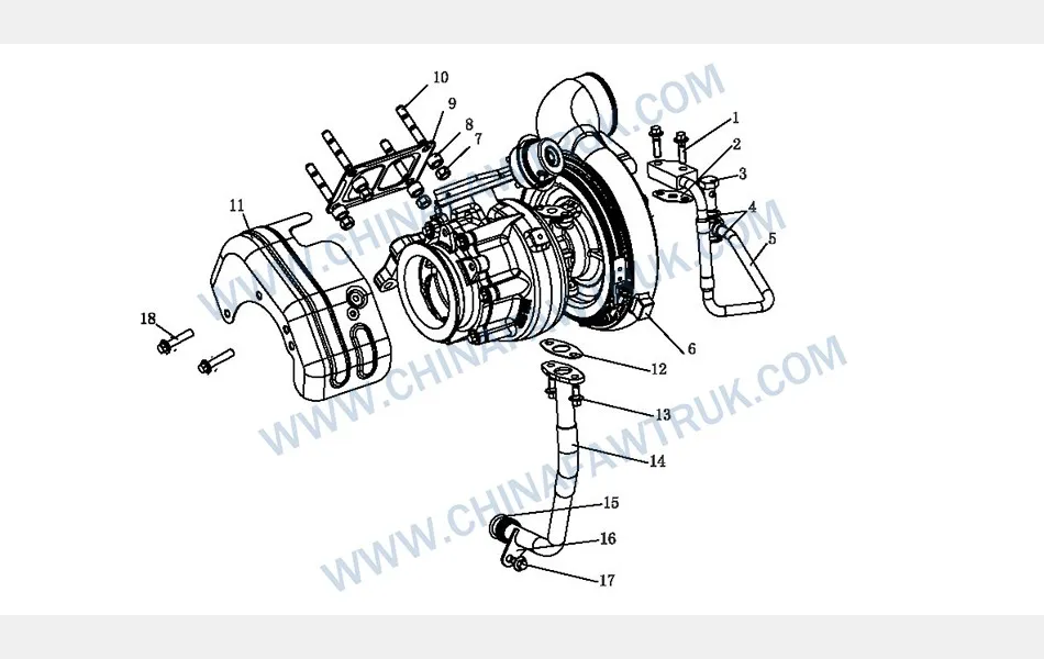
Le tableau suivant fournit l'intégralité, ventilation détaillée de tous les composants identifiés dans le « Turbocompresseur »’ schéma du tracteur FAW CA4251P66K24T1A3E5. Un service complet du Turbocompresseur FAW nécessite tous les nouveaux joints, joints toriques, et des goujons.
| Marque | Partie no. | Nom de la pièce | Quantité |
|---|---|---|---|
| 1 | Q1840830 | Boulon à bride hexagonale, tige grossière (Modèle standard) | 2 |
| 2 | 1118063-D6 | Joint – tuyau d'arrivée d'huile | 1 |
| 3 | Q/XC3451.1M16X1.5 | Boulon banjo | 1 |
| 4 | Q / WC3403-94(16X22) | Joint | 2 |
| 5 | 1118060-91W | Ensemble de tuyau d'entrée d'huile de turbocompresseur (selon l'échantillon) | 1 |
| 6 | 1118010-91W-C00 | Ensemble de turbocompresseur à turbine | 1 |
| 7 | 1118073-29D | Noix – turbocompresseur | 4 |
| 8 | 1118014-53D | Manche – turbocompresseur | 4 |
| 9 | 1118013A81D | Joint de turbocompresseur | 1 |
| 10 | 1118051-53D | Goujon à double tête de turbocompresseur | 4 |
| 11 | 1118031-1509 | Bouclier thermique du turbocompresseur | 1 |
| 12 | 1118094-29D | Joint – tuyau de retour d'huile du turbocompresseur | 1 |
| 13 | Q1840812 | Boulon à bride hexagonale, tige grossière (Modèle standard) | 1 |
| 14 | 1118080-2000 | Ensemble de tuyau de retour d'huile de turbocompresseur | 1 |
| 15 | Q07343236C | Joint torique pneumatique hydraulique en caoutchouc | 1 |
| 16 | 1118083-81D | Serrer – tuyau de retour d'huile du turbocompresseur | 1 |
| 17 | Q1840612 | Boulon à bride hexagonale, tige grossière (Modèle standard) | 1 |
| 18 | Q1840816 | Boulon à bride hexagonale, tige grossière (Modèle standard) | 2 |
Les spécifications pour le Turbocompresseur FAW sont définis par sa grande vitesse, fonctionnement à haute température, nécessitant un système de montage robuste, lubrification, et protection thermique. L'ensemble Turbocompresseur FAW l'assemblage est une unité équilibrée avec précision.
| Demande de véhicule | FAW Jiefang CA4251P66K24T1A3E5 6×4 Tracteur |
| Groupe de composants | Turbocompresseur FAW |
| Assemblage principal P/N | 1118010-91W-C00 |
| Système de roulement | Roulement à journaux flottant (Lubrifié à l'huile & Refroidi) |
| Système de montage | 4-Goujon (1118051-53D) avec des noix (1118073-29D) & Joint (1118013A81D) |
| Système d'alimentation en huile | Tuyau d'entrée haute pression (1118060-91W) avec joints banjo (Q / WC3403-94) |
| Système de retour d'huile | Tuyau d'alimentation par gravité basse pression (1118080-2000) avec joint (1118094-29D) |
| Gestion thermique | 1x Bouclier thermique du turbocompresseur (1118031-1509), 4x Manches (1118014-53D) | Manche
| Fonction principale | Utilise l'énergie des gaz d'échappement pour comprimer l'air d'admission (induction forcée), augmentation de la puissance et de l'efficacité du moteur. |
Pièces FAW, y compris l'ensemble bloc-cylindres, sont emballés avec soin pour garantir une livraison en toute sécurité. Chaque composant est sécurisé dans des matériaux de protection pour éviter tout dommage pendant le transport. Le réseau logistique garantit des expéditions ponctuelles dans le monde entier, soutenir des opérations de maintenance efficaces. Vous trouverez ci-dessous une image illustrant l'emballage standard des pièces de camion FAW., mettant en valeur l’attention portée aux détails dans la manipulation et le stockage.

Cette approche d'emballage minimise le risque de corrosion ou de dommages causés par les chocs., s'assurer que les pièces comme l'ensemble bloc-cylindres FAW arrivent en parfait état. Les clients peuvent compter sur la logistique de FAW pour une qualité et une fiabilité constantes.


