


by 


Welcome to this expert deconstruction of the FAW J6P Fuel Supply System (Chapter 23). This is the complete “High-Pressure Common Rail” (HPCR) assembly for the FAW Jiefang CA3250P66K2L1T1E 6×4 dump truck.
This is not a simple fuel line; it is a complex “Logic Assembly” of 50 component types, engineered for one purpose: to create and control immense pressure.
The “logic” of this FAW J6P Fuel Supply System is to draw fuel, filter it, pressurize it to over 25,000 PSI, and inject it as a microscopic, atomized mist directly into the cylinders at the precise microsecond it is needed.
The “Common Rail Logic” is what defines this FAW J6P Fuel Supply System. Unlike old systems, the ‘Fuel injection pump’ (Comp 1) does not *time* the injection; it only “generates pressure.” This immense pressure is stored in the “common rail” (the high-pressure pipes, Comp 35-42). This “logic” allows the ‘Injectors’ (Comp 18) to be electronically controlled, independent of the pump. This “Multi-Shot Injection Logic” (firing multiple, tiny injections per power stroke) is what gives the engine its quiet operation, its low-end torque, its fuel efficiency, and its low emissions.
This expert guide is an essential resource for engine technicians, fuel system specialists, and parts managers. We will deconstruct the entire 50-component group into its four primary “logic” systems: the “Low-Pressure & Filtration Logic” (the priming pump and filter), the “High-Pressure Generation Logic” (the main injection pump), the “High-Pressure Distribution Logic” (the common rail pipes), and the critical “Injection & Return Logic” (the injectors and return lines). This is the complete guide to the FAW J6P Fuel Supply System.
This group’s “logic” is to pull fuel from the tank, “prime” the system, and provide “Absolute Filtration” before the fuel ever reaches the expensive high-pressure pump.
1. Component: ‘Rotary-style hand-priming pump assy’ (1117010-29D)
This (Comp 49) is the “Serviceability Logic.” The FAW J6P Fuel Supply System is “self-bleeding” during normal operation, but after a filter change, the lines are full of air. This “hand-priming” pump’s “logic” is to allow a technician to manually *pull* fuel from the tank, *push* it through the ‘Fuel filter’ (Comp 28), and *bleed* all the air out of the system. Starting the engine with air in the lines can damage the high-pressure pump.
2. Component: ‘Fuel filter assy’ (1012010-36D)
This (Comp 28) is the “System Protection Logic.” This is the “gatekeeper” for the entire FAW J6P Fuel Supply System. High-Pressure Common Rail (HPCR) components have tolerances measured in *microns*. A single grain of sand or a drop of water will *instantly* destroy the ‘Fuel injection pump’ (Comp 1) or the ‘Injectors’ (Comp 18). This “Absolute Filtration Logic” means this filter must remove 99.9% of all water (via an integrated separator) and all particulate matter down to 2-5 microns. A cheap, low-quality filter is the number one cause of FAW J6P Fuel Supply System failure.
This group represents the “muscle” of the FAW J6P Fuel Supply System. Its sole function is to generate over 25,000 PSI of fuel pressure.
1. Component: ‘Fuel injection pump assy’ (1111010C31E)
This (Comp 1) is the “Pressure Logic.” This is a high-precision, “positive displacement” pump (likely a 3-piston radial pump). It takes the “low-pressure” (60-90 PSI) fuel from the filter (Comp 28) and compresses it to an immense 25,000+ PSI. Its “self-lubrication” logic is that it uses the diesel fuel itself as its *only* lubricant. This is another reason why the ‘Fuel filter’ (Comp 28) is so critical.
2. Component: ‘Fuel injector drive gear’ (1111216-59D)
This (Comp 7) is the “Drive Logic.” This high-pressure pump is not electric. It is “gear-driven” directly from the engine’s internal “Timing Gear Train.” This “Gear-Drive Logic” is a “life-of-the-engine” solution, as it is 100% reliable and perfectly timed with the engine’s rotation.
3. Components: ‘Support-fuel injection pump’ (1111101-31E) & ‘Bracket’ (1111102-29D)
These brackets (Comp 31 & 34) are the “Alignment Logic.” The ‘Drive gear’ (Comp 7) must mesh *perfectly* with the engine’s timing gear. These heavy-duty, cast brackets bolt to the engine block and provide a rigid, precision-machined mounting flange that guarantees this perfect alignment.
4. Components: ‘Lube oil pipe assy’ (1104060-29D) & ‘Hollow bolt’ (1104066-367)
This (Comp 10 & 11) is the “Pump Lubrication Logic.” While the *pumping* side of the HPCR pump is fuel-lubricated, its “drive” side (with its own bearings and camshaft) is lubricated by *engine oil*. This pipe’s “logic” is to “tap” clean oil from the engine block and feed it directly to the pump’s bearings, ensuring its long-term durability. This is a critical link for the FAW J6P Fuel Supply System.
This group forms the “Common Rail” itself. Its “logic” is to act as a “pressure reservoir” or “accumulator,” storing the 25,000+ PSI from the pump and distributing it to all six injectors.
1. Components: ‘High-pressure fuel pipe assy’ (Cyl 1-6) (1129010… to …1129060-31E)
These (Comp 35-40) are the six individual “injector lines.” These are the most critical pipes in the FAW J6P Fuel Supply System. Their “logic” is “Identical Length.” They are *all* precisely bent to be the exact same length. This is crucial. If one pipe were shorter, the “pressure waves” from the injector firing would be different, causing Cyl 1 to get a different pressure “pulse” than Cyl 6. By making them identical, the “pressure-wave logic” is balanced, ensuring every cylinder gets the *exact* same fuel, for a smooth, balanced engine.
2. Components: ‘High-pressure fuel pipe clip/base/gasket’ (1129100-29D, etc.)
This group (Comp 41-48) is the “NVH & Safety Logic.” The six high-pressure pipes (Comp 35-40) “throb” violently with every injection event. If allowed to touch each other or the engine, they would “chafe,” vibrate, and develop a “fatigue crack.” A high-pressure fuel leak at 25,000 PSI is not a “drip”—it is an *atomized*, highly-flammable mist that will instantly cause a massive engine fire. The “logic” of these clips and brackets is to hold every pipe perfectly rigid and isolated, preventing this critical failure in the FAW J6P Fuel Supply System.
This final group’s “logic” is to perform the “final event”: injecting the high-pressure fuel into the cylinder.
1. Component: ‘Injector’ (1112010-31E)
This (Comp 18) is the “Atomization Logic.” It is a high-speed, electronically-controlled (solenoid or piezo) needle valve. When the ECU commands, it opens for a few *microseconds*. The 25,000+ PSI pressure forces the fuel through microscopic holes in its nozzle, “atomizing” it into a vapor-like mist that ignites instantly for maximum power.
2. The “Sealing” Logic: ‘Injector gasket’ (1112306-29D) & ‘O-ring’ (1112014-29D)
The injector (Comp 18) must be sealed from two things. The ‘Gasket’ (Comp 17) is a copper “crush washer” at the bottom. Its “logic” is to seal the 2000+ PSI of *combustion pressure* out. The ‘O-ring’ (Comp 19) is a rubber seal at the top. Its “logic” is to seal the low-pressure “fuel return” *in*, preventing fuel from leaking onto the hot engine.
3. The “Clamping” Logic: ‘Injector presser plate’ (1112013-29D) & ‘Bolt’ (1112011-29D)
This “Clamping Logic” is what holds the injector in its bore. The ‘Bolt’ (Comp 21) pulls up on the ‘Presser plate’ (Comp 20), which pivots and creates a high “downward” force on the injector. This force is what “crushes” the ‘Gasket’ (Comp 17) to create the combustion-proof seal.
4. The “Return” Logic: ‘Fuel injector return pipe assy’ (1104050-29D)
This (Comp 13) is the “Bypass Cooling Logic.” The HPCR pump and injectors “bypass” a large amount of fuel to cool and lubricate their own moving parts. This ‘Return pipe’ “logic” is to collect all this “used” fuel from the injectors and the pump and route it safely back to the fuel tank. This is a vital part of the FAW J6P Fuel Supply System‘s thermal management.
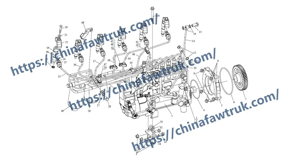
The following table provides the complete, detailed breakdown of all 50 component types in the FAW J6P Fuel Supply System for the FAW Jiefang CA3250P66K2L1T1E 6×4 dump truck.
| Mark | Part No. | Part Name | Quantity |
|---|---|---|---|
| 1 | 1111010C31E (1111010-675-0000TH) | Fuel injection pump assy | 1 |
| 2 | CQ1201030 | Double-ended stud | 4 |
| 3 | CQ39610 | Hexagon flange nut | 4 |
| 4 | CQ73421000C | O-ring for pneumatic | 1 |
| 5 | 1111228-30E (1111228-633-0000) | Check valve – fuel pump | 1 |
| 6 | CQ73421500C | O-ring for pneumatic | 1 |
| 7 | 1111216-59D (1111216-630-0000) | Fuel injector drive gear | 1 |
| 8 | Q1841045 | Hexagon flange bolt | 3 |
| 9 | Q1841030 | Hexagon flange bolt | 2 |
| 10 | 1104060-29D | Lube oil pipe assy | 1 |
| 11 | 1104066-367 | Hollow bolt – lube oil pipe assy | 1 |
| 12 | CQ72310T5 | Gasket | 1 |
| 13 | 1104050-29D | Fuel injector return pipe assy | 1 |
| 14 | CQ72314T5 | Gasket | 2 |
| 15 | 1104073-D6 | Hollow bolt – oil return pipe | 1 |
| 16 | Q1821090 | Hexagon flange stud bolt | 2 |
| 17 | 1112306-29D | Injector gasket | 6 |
| 18 | 1112010-31E (1112010-610-0000J) | Injector | 6 |
| 19 | 1112014-29D | O-ring | 6 |
| 20 | 1112013-29D | Injector presser plate | 6 |
| 21 | GB 849 8 | Spherical gasket | 6 |
| 22 | 1112011-29D | Injector presser plate | 6 |
| 23 | 1112030-29D | High pressure pipe joint assy | 6 |
| 24 | 1112032-29D | O-ring | 6 |
| 25 | 1112031-29D | Intermediate pressure sealing ring – high pressure pipe joint | 6 |
| 26 | 1104030-29D | Fuel pipe assy (I) | 1 |
| 27 | CQ72312T5 | Gasket | 2 |
| 28 | 1111069-29D | Clamping bolt | 1 |
| 29 | 1104040-29D | Fuel pipe assy (II) | 1 |
| 30 | 1111 055-29D | Turbocharger fuel pipe assy | 1 |
| 31 | 1111102-29D | Bracket-fuel injection pump | 1 |
| 32 | Q1841025 | Hexagon flange bolt | 2 |
| 33 | Q1841020 | Hexagon flange bolt | 2 |
| 34 | 1111101-31E (1111101-63J-0000) | Support-fuel injection pump | 1 |
| 35 | 1129010-31E (1129010A63J-0000) | First high-pressure fuel pipe assy | 1 |
| 36 | 1129020-31E (1129020A63J-0000) | Second high-pressure fuel pipe assy | 1 |
| 37 | 1129030-31E (1129030A63J-0000) | Third high-pressure fuel pipe assy | 1 |
| 38 | 1129040-31E (1129040A63J-0000) | Fourth high-pressure fuel pipe assy | 1 |
| 39 | 1129050-31E (1129050A63J-0000) | Fifth high-pressure fuel pipe assy | 1 |
| 40 | 1129060-31E (1129060A63J-0000) | Sixth high-pressure fuel pipe assy | 1 |
| 41 | 1129100-29D | High-pressure fuel pipe clip assy (I) | 1 |
| 42 | 1129150-29D | High-pressure fuel pipe clip assy (VI) | 1 |
| 43 | 1129130-29D | High-pressure fuel pipe clip assy (IV) | 1 |
| 44 | 1129123-29D | High-pressure fuel pipe base plate (III) | 1 |
| 45 | 1129127-29D | High-pressure fuel pipe presser plate (III) | 1 |
| 46 | 1129129-29D | High-pressure fuel pipe gasket (III) | 1 |
| 47 | 1129110-29D | High-pressure fuel pipe clip assy (II) | 1 |
| 48 | 1129140-29D | High-pressure fuel pipe clip assy (V) | 1 |
| 49 | 1117010-29D | Rotary-style hand-priming pump assy | 1 |
| 50 | CQ1460810 | Combination bolt | 5 |
The specifications for the FAW J6P Fuel Supply System are defined by its function as a high-pressure common rail (HPCR) injection system.
| Vehicle Application | FAW Jiefang CA3250P66K2L1T1E 6×4 Dump Truck |
| System Group | FAW J6P Fuel Supply System (HPCR) |
| System Type | High-Pressure Common Rail (HPCR) |
| Primary Logic | Pressurization (Pump), Storage (Rail), Atomization (Injector) |
| High Pressure Pump | ‘Fuel injection pump assy’ (1111010C31E) |
| Pump Drive System | ‘Fuel injector drive gear’ (1111216-59D) – Gear-Driven |
| Injector Component | ‘Injector’ (1112010-31E) – Qty 6 |
| Injector Sealing (Combustion) | ‘Injector gasket’ (1112306-29D) – Qty 6 |
| Injector Clamping | ‘Injector presser plate’ (1112013-29D) – Qty 6 |
| High Pressure Lines | ‘High-pressure fuel pipe assy’ (1129010… to …060-31E) – Qty 6 |
| Line Securing System | ‘High-pressure fuel pipe clip/base/gasket’ (11291xx-29D series) |
| Filtration & Priming | ‘Fuel filter assy’ (1012010-36D), ‘Hand-priming pump’ (1117010-29D) |
| Return System | ‘Fuel injector return pipe assy’ (1104050-29D) |
FAW parts, including the Cylinder Block Assembly, are packaged with care to ensure safe delivery. Each component is secured in protective materials to prevent damage during transit. The logistics network guarantees timely shipments worldwide, supporting efficient maintenance operations. Below is an image illustrating the standard packaging for FAW truck parts, showcasing the attention to detail in handling and storage.

This packaging approach minimizes the risk of corrosion or impact damage, ensuring that parts like the FAW Cylinder Block Assembly arrive in perfect condition. Customers can rely on FAW’s logistics for consistent quality and reliability.


