Anti-Lock Braking System Control Unit: Orchestrating 4 Critical Nodes for Fail-Safe Arctic Braking Logic
The Anti-Lock Braking System Control Unit (ECU) is the computational brain behind the safety architecture of the FAW CA3250P66K24L1TE5Z dump truck. In the unpredictable conditions of the Russian heavy transport sector, where black ice and packed snow are constant threats, this logic assembly processes velocity data in milliseconds to prevent wheel lockup. By modulating pneumatic pressure through a network of solenoid valves, the Anti-Lock Braking System Control Unit maintains steering authority and vehicle stability during panic stops, ensuring that the driver retains absolute control even at -50°C.
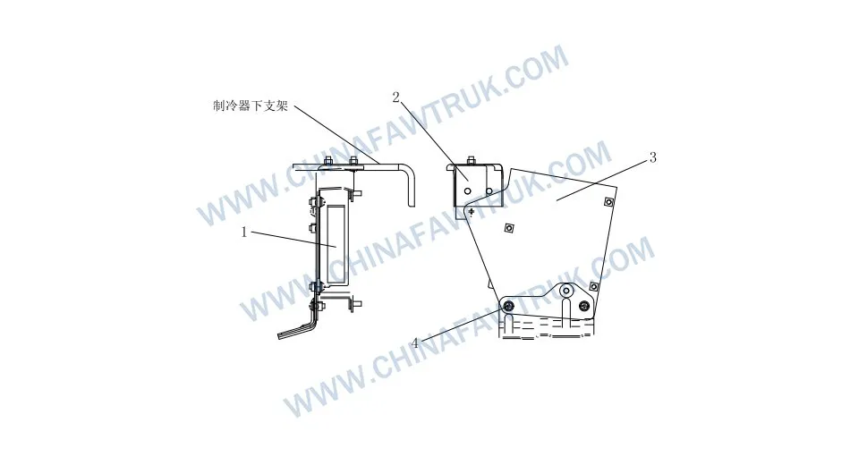
Anti-Lock Braking System Control Unit
| No. |
Part Number |
Part Name |
Qty |
| 1 | 3605115-50A | Anti-lock Braking System Control Unit Assembly | 1 |
| 2 | 3605125-50A | ABS Control Unit Upper Bracket Assembly | 1 |
| 3 | 3605135-60A | Control Unit Combination Bracket Assembly | 1 |
| 4 | Q2360616 | Cross Recessed Pan Head Screw and Washer Assembly | 8 |
The Digital Nervous System of Heavy-Duty Safety
The Anti-Lock Braking System Control Unit is much more than a simple circuit board; it is a ruggedized computer engineered for one of the harshest operating environments on earth. This “50A” spec unit is specifically calibrated for the friction coefficients found in Russian winter conditions. It constantly monitors input from the Wheel Speed Sensor Assembly located at each wheel end. By comparing the rotational velocity of the individual wheels against the vehicle’s estimated speed, the Anti-Lock Braking System Control Unit can detect the onset of a skid before the driver is even aware of the danger.
Once a lockup condition is detected, the Anti-Lock Braking System Control Unit takes command of the pneumatic system. It sends rapid-fire electrical pulses to the Anti-lock Solenoid Valve & Pipe Joint Assy, modulating the air pressure sent to the brake chambers. This pulsing action, occurring up to 15 times per second, allows the tire to maintain rolling traction, which is essential for steering. Without the precise intervention of the Anti-Lock Braking System Control Unit, a fully loaded dump truck on an icy grade becomes an uncontrollable sled.
The durability of the Anti-lock Braking System Control Unit Assembly (Part No. 3605115-50A) is paramount. The internal electronics are potted in a vibration-resistant gel that protects delicate solder joints from the low-frequency shaking of the diesel engine and the high-frequency shocks of the road. Furthermore, the enclosure is sealed against moisture ingress. In the Russian Arctic, the temperature differential between the warm cab and the frozen exterior can create condensation; the Anti-Lock Braking System Control Unit is designed to remain watertight to prevent short circuits that would disable the safety system.
Structural Mounting and Vibration Isolation
The reliability of the Anti-Lock Braking System Control Unit is heavily dependent on how it is physically integrated into the cab structure. The assembly utilizes a two-stage mounting system consisting of the ABS Control Unit Upper Bracket Assembly (Part No. 3605125-50A) and the Control Unit Combination Bracket Assembly (Part No. 3605135-60A). These brackets function as a mechanical filter, isolating the sensitive ECU from the harshest chassis vibrations. Rigid mounting of electronics in a heavy-duty truck often leads to early failure due to component fatigue; the Anti-Lock Braking System Control Unit mounting logic mitigates this risk effectively.
The brackets are constructed from stamped steel, treated with a corrosion-resistant coating to withstand the humid environment inside the cab. They position the Anti-Lock Braking System Control Unit in a location that is accessible for diagnostics but protected from physical damage, such as kicks from the driver or loose objects in the cabin. The orientation of the ECU is also critical; it is mounted to ensure that the wiring harness connectors face downwards or sideways, preventing any condensation that might form on the casing from dripping into the connector pins.
Securement of the ECU to these brackets is achieved using the Cross Recessed Pan Head Screw and Washer Assembly (Part No. Q2360616). These 8 screws provide a distributed clamping force that holds the plastic housing of the ECU firmly without cracking it. The integrated washers prevent the screws from backing out under vibration. In the maintenance of the Anti-Lock Braking System Control Unit, checking the tightness of these screws is a simple but vital step to ensure the brain of the braking system remains secure.
System Integration and Signal Logic
The Anti-Lock Braking System Control Unit serves as the central hub for a vast array of peripheral components. It continuously polls the resistance and voltage signals from the Wheel Speed Sensor Assembly at all six wheel positions. If a sensor wire is cut or a sensor head is covered in conductive brake dust, the Anti-Lock Braking System Control Unit logic immediately identifies the specific fault location and triggers a diagnostic code. This intelligent monitoring capability drastically reduces troubleshooting time for fleet mechanics working in cold, difficult conditions.
Beyond input monitoring, the Anti-Lock Braking System Control Unit manages the power output to the modulator valves. The system distinguishes between different levels of slip. On a split-friction surface (e.g., ice on the left, tarmac on the right), the ECU executes a “modified individual control” strategy. It limits the braking force on the high-traction side to prevent the vehicle from yawing or spinning out. This sophisticated algorithm is embedded within the Anti-lock Braking System Control Unit Assembly and is key to the J6P’s reputation for stability.
The wiring interface connecting the Anti-Lock Braking System Control Unit to the rest of the truck relies on the integrity of the Cab Pipe Harness Assembly. The connectors are designed with multi-lip silicone seals to prevent water intrusion. A single corroded pin in the main connector can lead to intermittent ABS failure. Therefore, the mechanical protection provided by the Control Unit Combination Bracket Assembly also serves to relieve strain on the wiring harness, preventing the weight of the cables from pulling on the connector terminals.
Diagnostics and Replacement Protocols
When the ABS warning light illuminates, the Anti-Lock Braking System Control Unit is the first port of call for diagnostics. Modern units support OBD access, allowing technicians to read fault codes directly. However, “ECU failure” is often a misdiagnosis for power supply issues. Before condemning the expensive Anti-lock Braking System Control Unit Assembly, it is crucial to check the Battery Cover Plate and main fuses to ensure the unit is receiving clean, stable voltage. Voltage drops caused by cold batteries in winter can cause the ECU to reset or behave erratically.
If replacement is necessary, the installation of the new Anti-Lock Braking System Control Unit requires adherence to static safety procedures. The electronic components are sensitive to electrostatic discharge (ESD). Furthermore, when securing the unit to the ABS Control Unit Upper Bracket Assembly, the Cross Recessed Pan Head Screw fasteners should be tightened in a cross pattern to avoid warping the housing. Over-tightening can crack the mounting tabs, while under-tightening can lead to vibration damage.
Finally, after installing a new Anti-Lock Braking System Control Unit, a reconfiguration or learning procedure may be required to match the ECU to the specific tire size and tone ring tooth count of the vehicle. This ensures the speed calculations are accurate. Using a genuine FAW Anti-lock Braking System Control Unit Assembly guarantees that the firmware is compatible with the rest of the truck’s CAN bus architecture, preventing communication errors with the engine and transmission controllers.
Conclusion: The Guarantee of Intelligent Safety
The Anti-Lock Braking System Control Unit is the silent guardian of the FAW J6P dump truck. While the massive brake drums and shoes do the physical work, it is this compact logic assembly that ensures that force is applied safely and effectively. The 4 components listed—the ECU, brackets, and screws—form a secure, vibration-isolated platform that allows the digital brain to survive and function in the harshest conditions imaginable.
For fleet managers, the Anti-Lock Braking System Control Unit represents the difference between a controlled stop and a catastrophic accident. Ensuring that this unit is securely mounted, kept dry, and properly powered is the most cost-effective safety insurance available. By utilizing genuine FAW replacement parts for the logic assembly and its brackets, operators ensure that their vehicles retain the high-tech safety edge engineered into them at the factory.
Packaging and Logistics
FAW parts, including the Cylinder Block Assembly, are packaged with care to ensure safe delivery. Each component is secured in protective materials to prevent damage during transit. The logistics network guarantees timely shipments worldwide, supporting efficient maintenance operations. Below is an image illustrating the standard packaging for FAW truck parts, showcasing the attention to detail in handling and storage.
This packaging approach minimizes the risk of corrosion or impact damage, ensuring that parts like the FAW Cylinder Block Assembly arrive in perfect condition. Customers can rely on FAW’s logistics for consistent quality and reliability.


