


by 


Welcome to this critical technical guide on the FAW Turbocharger (Part No. 1118010-91W-C00), the single most important power-adder component for the FAW Jiefang CA4251P66K24T1A3E5 6×4 diesel semi-trailer tractor. This is the heart of the engine’s forced induction system.
The FAW Turbocharger is responsible for forcing a high volume of compressed air into the engine’s cylinders, allowing for a much larger fuel burn, which dramatically increases horsepower and torque. This component is a precision-engineered turbine that spins at speeds exceeding 150,000 RPM.
This guide is an essential resource for professional technicians, engine specialists, and parts managers. We will deconstruct the entire FAW Turbocharger assembly and its critical ancillary systems, including the high-temperature mounting, the high-pressure oil feed, and the oil return lines, down to the smallest serviceable unit.
The core component is the ‘Turbine Turbocharger Assembly’ (1118010-91W-C00). This is the main FAW Turbocharger unit. It is a highly-balanced, precision assembly consisting of two main halves: the “hot side” and the “cold side.”
**The Turbine (Hot Side):** The engine’s hot exhaust gases are funneled directly into the turbine housing. This high-pressure gas spins a turbine wheel, which is made from an exotic, high-temperature superalloy like Inconel, capable of withstanding over 900°C (1650°F). This is the “engine” that powers the entire FAW Turbocharger.
**The Compressor (Cold Side):** The turbine wheel is connected via a hardened steel shaft to a “compressor wheel” on the cold side. This wheel is typically milled from a solid billet of aluminum. As it spins, it draws in fresh, filtered air and compresses it (creating “boost”), forcing it into the engine’s intercooler and intake manifold.
**The CHRA (Center Hub Rotating Assembly):** The shaft connecting these two wheels spins at incredible speeds in a “floating” journal bearing system. This bearing, at the heart of the FAW Turbocharger, does not physically touch the shaft; it rides on a microscopic film of high-pressure engine oil, which both lubricates and cools it. The integrity of this oil film is the single most important factor in FAW Turbocharger longevity.
Mounting the FAW Turbocharger is an extreme-heat challenge. It bolts directly to the exhaust manifold, which is the hottest part of the engine. To handle this, the system relies on specialized hardware. The four ‘Turbocharger double-headed stud bolts’ (1118051-53D) are threaded into the exhaust manifold first. These are made of high-tensile, heat-resistant steel.
The ‘Turbocharger gasket’ (1118013A81D) is placed onto these studs. This is not a paper gasket; it is a Multi-Layer Steel (MLS) gasket, designed to be crushed between the manifold and the FAW Turbocharger turbine housing. It must contain the high-pressure, superheated exhaust gases, preventing leaks. A leaking turbine inlet gasket will “whistle” and cause a severe loss of boost pressure.
The FAW Turbocharger is then slid onto the studs, followed by the four ‘Sleeve – turbocharger’ (1118014-53D). These sleeves are critical; they act as precision spacers and, more importantly, thermal isolators, helping to keep the nuts from absorbing the full heat of the turbine housing. Finally, the four ‘Nut – turbocharger’ (1118073-29D) are torqued down. These are special “lock nuts,” often made of distortion-locking steel, designed to resist loosening under extreme heat cycles and vibration. This entire set of hardware is essential for a reliable FAW Turbocharger installation.
A FAW Turbocharger spinning at 150,000 RPM will be destroyed in less than five seconds without oil. The ‘Turbocharger oil inlet pipe assembly’ (1118060-91W) is its lifeline. This is a pre-formed, rigid steel pipe designed to tap into a high-pressure oil gallery on the engine block.
This pipe feeds the coolest, cleanest, highest-pressure oil directly to the CHRA’s journal bearing. The design of this FAW Turbocharger oil feed is critical; it must be free of kinks, cracks, or any debris.
This high-pressure connection is sealed using specialized banjo fittings. The ‘Banjo bolt’ (Q/XC3451.1 M16X1.5) is a hollow bolt that allows oil to flow through it. It is sealed by the two ‘Gaskets’ (Q/WC3403-94(16X22)). These are soft copper or aluminum crush washers. One gasket is placed on each side of the banjo fitting. When the bolt is torqued, these washers deform, creating a perfect, high-pressure seal. These gaskets are single-use. Re-using them will cause a high-pressure oil leak, starving the FAW Turbocharger and creating a massive fire risk as oil sprays onto the red-hot turbine housing. This is a critical service point for the FAW Turbocharger.
After the oil is forced through the FAW Turbocharger bearing, it is no longer under pressure. It must then drain *out* of the CHRA and back to the oil pan. This is the job of the ‘Turbocharger oil return pipe assembly’ (1118080-2000).
This is a large-diameter, low-pressure pipe. Its design is critical: it must be as wide as possible and routed with a constant, downward slope (gravity feed). Any kink, clog, or low spot in this return line will cause the oil to back up inside the FAW Turbocharger‘s center housing.
When this backup occurs, the built-up oil pressure has nowhere to go but past the FAW Turbocharger‘s internal “piston ring” seals. This is a primary cause of “blue smoke” from the exhaust, as oil is forced into the hot turbine housing and burned. It can also force oil into the “cold side,” fouling the intercooler. The ‘Clamp – turbocharger oil return pipe’ (1118083-81D) is used to secure this pipe.
This return pipe is sealed at the FAW Turbocharger housing by the ‘Gasket – turbocharger oil return pipe’ (1118094-29D), and at the engine block by the ‘Hydraulic pneumatic O-ring rubber seal’ (Q07343236C). Both seals are critical to prevent external leaks. This entire return path is a key part of the FAW Turbocharger system’s health.
The ‘Turbocharger heat shield’ (1118031-1509) is a stamped metal plate. Its function is to sit between the red-hot turbine housing and the “cold” compressor housing, or between the turbine and the engine block. It blocks the intense radiant heat from the “hot side” of the FAW Turbocharger.
This shield prevents this extreme heat from “coking” (burning) the oil inside the center bearing housing after the engine is shut off. This “heat soak” is a major cause of FAW Turbocharger failure. This shield, along with other miscellaneous fasteners like the ‘Hex flange bolts’ (Q1840830, Q1840812, Q1840612, Q1840816), is used to secure the various pipes, clamps, and shields, ensuring the entire FAW Turbocharger assembly is free from vibration and protected from its own heat.
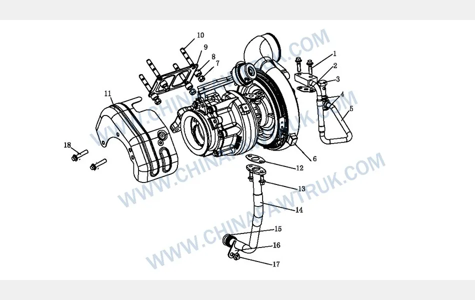
The following table provides the complete, detailed breakdown of all components identified in the ‘Turbocharger’ diagram for the FAW CA4251P66K24T1A3E5 tractor. A complete service of the FAW Turbocharger requires all new gaskets, o-rings, and studs.
| Mark | Part No. | Part Name | Quantity |
|---|---|---|---|
| 1 | Q1840830 | Hex flange bolt, coarse rod (Standard Type) | 2 |
| 2 | 1118063-D6 | Gasket – oil inlet pipe | 1 |
| 3 | Q/XC3451.1 M16X1.5 | Banjo bolt | 1 |
| 4 | Q/WC3403-94(16X22) | Gasket | 2 |
| 5 | 1118060-91W | Turbocharger oil inlet pipe assembly (as-per-sample) | 1 |
| 6 | 1118010-91W-C00 | Turbine Turbocharger Assembly | 1 |
| 7 | 1118073-29D | Nut – turbocharger | 4 |
| 8 | 1118014-53D | Sleeve – turbocharger | 4 |
| 9 | 1118013A81D | Turbocharger gasket | 1 |
| 10 | 1118051-53D | Turbocharger double-headed stud bolt | 4 |
| 11 | 1118031-1509 | Turbocharger heat shield | 1 |
| 12 | 1118094-29D | Gasket – turbocharger oil return pipe | 1 |
| 13 | Q1840812 | Hex flange bolt, coarse rod (Standard Type) | 1 |
| 14 | 1118080-2000 | Turbocharger oil return pipe assembly | 1 |
| 15 | Q07343236C | Hydraulic pneumatic O-ring rubber seal | 1 |
| 16 | 1118083-81D | Clamp – turbocharger oil return pipe | 1 |
| 17 | Q1840612 | Hex flange bolt, coarse rod (Standard Type) | 1 |
| 18 | Q1840816 | Hex flange bolt, coarse rod (Standard Type) | 2 |
The specifications for the FAW Turbocharger are defined by its high-speed, high-temperature operation, requiring a robust system for mounting, lubrication, and heat shielding. The entire FAW Turbocharger assembly is a precision-balanced unit.
| Vehicle Application | FAW Jiefang CA4251P66K24T1A3E5 6×4 Tractor |
| Component Group | FAW Turbocharger |
| Main Assembly P/N | 1118010-91W-C00 |
| Bearing System | Floating Journal Bearing (Oil Lubricated & Cooled) |
| Mounting System | 4-Stud (1118051-53D) with Nuts (1118073-29D) & Gasket (1118013A81D) |
| Oil Feed System | High-Pressure Inlet Pipe (1118060-91W) w/ Banjo Seals (Q/WC3403-94) |
| Oil Return System | Low-Pressure Gravity-Feed Pipe (1118080-2000) w/ Gasket (1118094-29D) |
| Thermal Management | 1x Turbocharger Heat Shield (1118031-1509), 4x Sleeves (1118014-53D) | Sleeve
| Primary Function | Uses exhaust gas energy to compress intake air (forced induction), increasing engine power and efficiency. |
FAW parts, including the Cylinder Block Assembly, are packaged with care to ensure safe delivery. Each component is secured in protective materials to prevent damage during transit. The logistics network guarantees timely shipments worldwide, supporting efficient maintenance operations. Below is an image illustrating the standard packaging for FAW truck parts, showcasing the attention to detail in handling and storage.

This packaging approach minimizes the risk of corrosion or impact damage, ensuring that parts like the FAW Cylinder Block Assembly arrive in perfect condition. Customers can rely on FAW’s logistics for consistent quality and reliability.


